Fred Circuits
- Solar Engine- Photopopper
- Shadow Protection
- Turbot
- Related Links
Ben Hitchcock designed the original Fred solar engine and photopopper. He provided this analysis:
Solar Engine
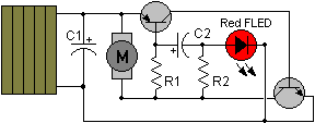
| Component Values | |
| C1 | 3000 uF |
| C2 | 0.22 uF |
| R1 | 3.3 K |
| R2 | 33 K |
Circuit Analysis
Fred robots, when set up in the 'photopopper' configuration, consist of two identical and almost completely independent solar engines. These SE's consist of three main parts:
1) FLED based oscillator2) Amplification circuitry
3) Latch
An explanation of each part follows.
1) FLED based oscillator -- This is the 'heart' of the Fred engine. It consists of a FLED, which is fed through a 33k resistor. When the FLED turns on, it sucks a large amount of current through the 33k resistor, and the voltage on the anode of the FLED lowers. When the FLED turns off, it sucks a lot less current, so the voltage on the anode rises. This means that you get a 2 Hz square wave on the anode of the FLED.
The amplitude of this square wave is dependent on two things: supply voltage, and ambient light. The more supply voltage, the larger the amplitude. More ambient light means the FLED won't suck as much current when it's ON, so the amplitude will decrease. Less light means more amplitude.
The final part of the FLED based oscillator is the 0.22 uF capacitor, which connects the square wave to the amplification circuitry. This capacitor is there to only allow the falling edge of the square wave 'through' to the amplification circuitry. This makes the Fred SE quite efficient. If you look at the voltage on the other side of the capacitor, it looks like a 2 Hz spike, with amplitude that is dependant on supply voltage, and ambient light. More volts and less light means a bigger spike.
2) Amplification circuitry -- This is the PNP transistor. Its job is to make the spike have more 'oomph', because the spike on its own isn't enough to drive the motor driver transistor. So the PNP is set up to amplify the spike as much as possible, and drive the motor driver transistor as hard as it can. The gain of this transistor is critical -- you need a gain of at least 150 or so for Fred to be reliable. I use BC327's because they have a gain of 300 - 400 (from memory).
3) Latch -- This is the combination of the NPN motor driver transistor, the 3.3k resistor, and the PNP transistor. When enough current comes down through the PNP transistor to turn the NPN slightly on, the circuit will 'feed back' through the 3.3k resistor and turn the PNP on harder. This turns the NPN on more, and you get a sudden cascade where the two transistors latch each other on. The motor is set up to spin whenever the NPN transistor is on. Once the two transistors are triggered, there isn't much that will turn them off, apart from the supply voltage dropping below the threshold for the circuit (which is somewhere around 1 Volt or so). When the supply voltage drops enough, the two transistors can't supply enough current to keep each other turned on, and so they both turn off at the same time.
And then the cycle repeats! The important parts to remember are:
1) The amplitude of the square wave (and therefore the 'spike') is dependant on supply voltage. Therefore the Fred solar engine won't trigger if the supply voltage isn't above 2.7 volts or so.
2) The amplitude of the square wave (and trigger) is also dependant upon how much ambient light there is. Therefore a Fred with full sunlight pouring into the FLED might not fire, and will therefore 'lock up'. This is why people put heat shrink around their FLEDs.
Photopopper
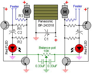
| Component Values | |
| C1 | 3000 uF |
| C2 | 0.22 uF |
| R1 | 3.3 K |
| R2 | 33 K |
| R3 | 1 K |
Once you understand how the independent solar engines work, you are ready to consider the dynamics of putting two Fred SE's together. These are coupled in two ways:
1) Electrically (through the supply rail)
2) Mechanically (the two SE's are physically connected together)
The electrical coupling means that both SE's will be constantly trying to trigger, but the first SE to trigger will make the supply voltage drop, and therefore stop the other SE from getting that tiny bit of extra voltage it needed to fire. In other words, the dark side fires first.
The mechanical coupling is quite loose, and means that if side 1 is in brightness then the side 2 will fire more often. After a while side 2 will turn the body of the Fred around, so that side 1 is 'darker' than it was before, and therefore more likely to fire first.
Bit tricky to explain properly, hopefully this helps.
Cheers,
Ben
Shadow Protection
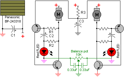
| Component Values | |
| C1 | > 1 F |
| C2 | 0.22 uF |
| C3 | 470 uF |
| R1 | 3.3 K |
| R2 | 33 K |
| R3 | 2.2 K |
Circuit Analysis
C3 provides enough power for the PNP transistors to latch the circuit. When C3 discharges, the Fred SE resets. C3 then charges from C1. This allows C1 to be a higher value, storing more power and keeping the voltage closer to the solar cell's peak power point.
The standard Fred SE continues to fire until the voltage in C1 falls below the forward voltage drop of the transistors. When this occurs, the two transistors cannot source the current needed to keep latched. Both of the transistors turn off and the SE resets.
This limits the total amount of capacitance on C1. Ideally, for the photopopper to be phototropic, C1 provides enough power for the SE that triggers to move the robot about 45-degrees. Any more than that and the popper ceases to effectively track the light.
Because the robot cannot store more energy than is needed for a single firing, the robot cannot ōsurviveö the light source being removed. A shadow, for instance, can deprive the robot of power. This modification corrects that by allowing the robot to store up enough energy for several pops after the light source is removed.
Turbot

The Fred Photopopper circuit can be adapted for a Turbot by using two solar cells with bypass diodes and replacing the C1 storage capacitor.
Arrange the two solar cells on the Turbot so that one is on the top and the other is on the bottom. This arrangement means that, during the range of motion, one solar cell will typically be shaded. Without the diodes, the total current will be limited by this shaded solar cell. The bypass diodes allow the current to bypass the shaded cell and increase the power available to the circuit.
The selection of the storage capacitor depends upon the desired behavior and the motors being used. The larger capacitor will be more energy efficient, but will be limited in behaviors (single firing equating to single tumble). Lower capacitor makes for a wider array of behaviors, however makes for more stress on the motor. The Turbot may even not tumble if the motor is a single geared motor, or not geared at all. The ideal motor for smaller capacitance is a worm-gear motor.
Related Links:
- Ben Hitchcock's Fred Page- Bug 'n' Bots Fred Kit