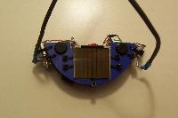
Electronics. Start out by gathering the FLEDs, PNP and NPN transistors.
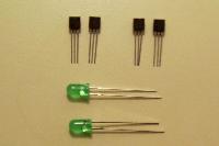
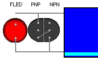
Mark the PNP transistor by cutting 2mm from its collector lead.
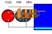
Super glue the PNP and NPN transistors together, face to face. Glue the FLED to the PNP. The FLEDs cathode is on the same side as the PNPís collector and the NPNís emitter.
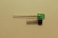
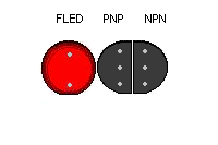
Solder the PNPís collector to the NPNís base.
Bend the PNPís emitter up on a 90-degree angle. Bend the FLEDís cathode and the NPNís emitter down on a 90-degree angle.
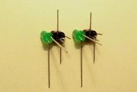
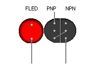
About 2 mm from the FLED, bend the cathode towards the transistors at a 90-degree angle. Solder the NPNís emitter to the FLEDís cathode. Clip the NPNís emitter clean, but leave the FLEDís cathode long.
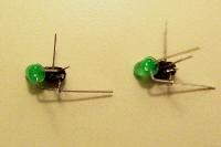
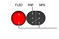
Solder the FLEDís cathode to the 4700 uF capacitorís cathode. Trim up the FLED clean.
Solder capacitorís anode to the PNPís emitter. Cut the PNP clean, but leave the capacitorís anode long. This will serve as the motorís positive mount.
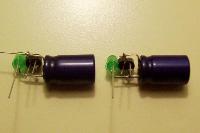
Take the 3.3K and 47K resistors. Wrap the 3.3K resistor lead around the 47K resistorís lead four times. Use a spot of super glue to keep the resistors together.
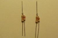
Now take the 0.47 uF capacitor. Super glue it down on top of the resistors. Wrap one lead around the 47K resistor, and the other lead around the 3.3K resistor.
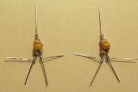
Solder the resistors and capacitor together where the parts are wrapped. Clip the 0.47 capacitors leads clean.
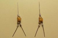
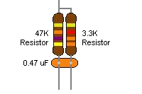
Solder the 47K resistorís top lead to the NPNís collector, and bottom lead to the FLEDís anode. Solder the 3.3K resistorís bottom lead to the PNPís base. Trim it clean, but leave about 2 mm hanging off the NPNís collector for the motorís negative mount.
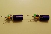
Remove the eject worm gear motor from the Solarbotics Cassette Mechanism kit. This requires you to unscrew it from the front and rear of the Cassette frame.
Drill a 1/16Ē hole into the white gear near the flat portion of the gear head. We will use the gear head and this hole to mount the Turbotís flagella.
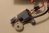
If you are using Hydro-X solder, switch to Rosin Core for any wire connections. Hydro-X will weaken the stranded wires and shorten the Turbotís lifespan.
On the first Fred Solar Engine, solder the motorís positive connection to the 4700 capacitorís anode. Solder the motorís negative connection to the NPNís collector / 47K resistor. Use heat shrink to ensure a solid connection, and trim the remaining leads clean.
Repeat on the second Fred Solar Engine, but reverse the motor connections. Solder the motorís negative connection to the 4700 capacitorís anode. Solder the motorís positive connection to the NPNís collector / 47K resistor.
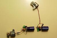
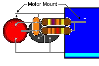
Cut three power wires, one black and two red. Cut the wires long as the longer connections are more convenient when building the body. We will shorten the wires during the final construction.
Solder the black power wire to the first diodeís anode. Solder a red power wire from the first diodeís cathode to the second diodeís anode. Solder a red power to the second diodeís cathode.
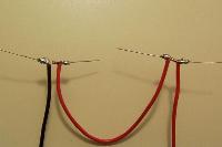
Place heat shrink tube over the power connections. Solder the diodes to the BP-3733 solar cells. The diodes are reverse biased, with the diodeís anode going to the solar cells cathode. Do this for both solar cells, wiring them in series.
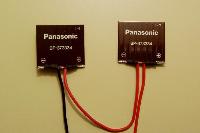
Test the solar cell / diode combination under a light source to make certain that you is getting the voltage. You should see slightly less than double the BP-3733ís voltage (~8 Ė 9V), and the same amount of current. As you move your hand across one cell or the other, the voltage will dip slightly.
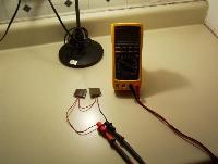
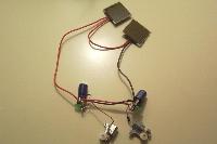
Wire the red positive power wire from the solar cells into the first SE 4700 capacitorís anode. Wire the black negative power wire from the solar cells into the second SE 4700 capacitorís cathode. Run power wires from the first to the second Fred Solar Engine. This forms the Fred popper.
Test the Fred Solar Engines once more under a light source. Both motors should turn.
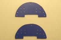
Mechanics. Cut two sections from 3mm Blue Sintra. Drill 1/8Ē holes for the wire ties. This forms the top and bottom body.
Feed four wire ties into the holes for the Fred Solar Engine. Mix up two-part epoxy. Place some epoxy between the wire ties. Slide the 4700 uF capacitor between the holes, then tighten up the wire ties to secure the Fred Solar Engine.
Note: It is important to get the Fred Solar Engine as far back as possible. This will ensure that the body protects it. If the SE hangs out past the front, then it is susceptible to shorts and being squashed.
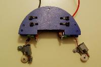
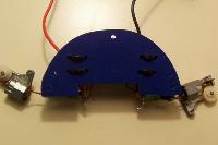
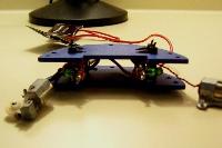
Test the Turbot once more under a light source. Both motors should turn. Clip the wires connecting the SEs and the solar cells. Mix up two part epoxy. Glue the solar cells between the wire ties that secure the 4700 uF capacitors.
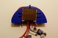
In the last step, you clipped the power wires running from the solar cell to the SEs. Trim these wires to fit the size of the body, resolder and secure with heat shrink and/or electrical tape.
Test to make certain that the SEs are still firing and that both motors turn.
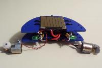
Now we will build the flagella, or the Turbot's arms. Cut two sections of 16 Gage wire, 16 cm long. I used the 5V power supply wire recycled from a desktop computer. Cover the wire with heat shrink tubing, leaving one end 1.5 to 2 cm uncovered.
Remove the ejector rod from the cassette mechanism. If you do not have this rod, or if you make a mistake, then a stiff paper clip will also work. Bend it so that the tip is down 2 mm on a 90-degree angle. Place this tip into the hole drilled in the worm gear motor. Where the gear wheel ends, bend the clip up away from the motor at a 90-degree angle. This is to give the flagella room to clear the motor casing. Finally, bend the rod 90-degrees down, about midway between the end of the gear and the end of the rod.
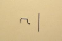
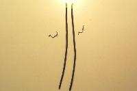
Most of the mechanical stresses will be on the gear motor, the rod, and the wire. Therefore, it is important to re-enforce these areas as much as possible.
Strip the wire and solder it to the rods. Ideally, the heat shrink should start where the rod ends [note: the photograph is incorrect as the heat shrink starts before the rod ends].
Cover the wire and the rod with a second layer of heat shrink. This will secure the rod to the wire, making for a solid flagella. Using a piece of heat shrink with a larger diameter, cover just the portion of the flagella where the rod meets the wire.
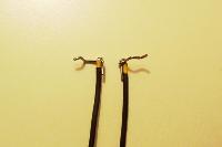
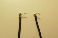
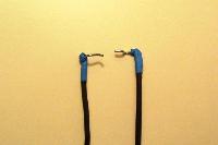
Mix up more two-part epoxy, place the flagella's rod into the hole on the gear, and glue the flagella into place. Take extreme care not to get epoxy on the gear teeth or the gear axel.
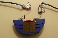
The last step attach the flagella to the body. Wire tie the motors to the body using the holes provided. Bend the flagella into shape. Place two tabs from the self-sticking cushion feet pack onto each half of the body to keep the turbot from flopping onto its solar cells.
