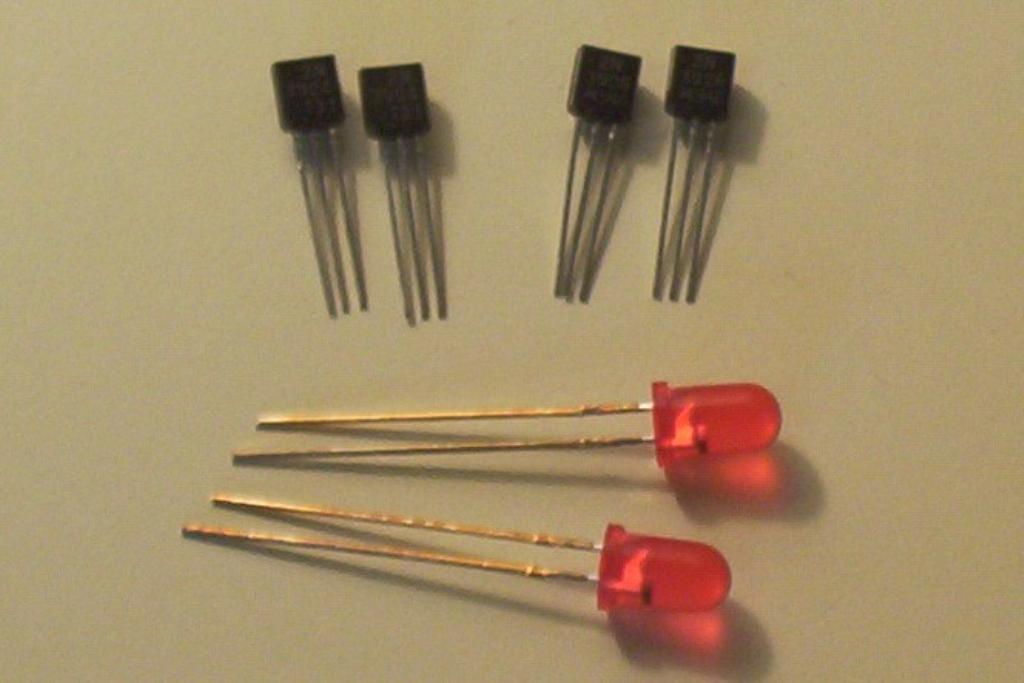
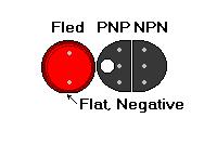
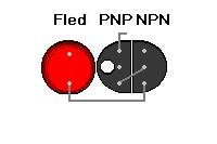
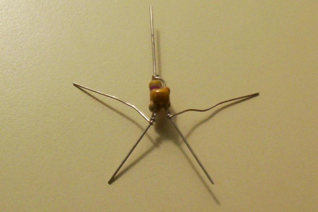
Start out by gathering the FLEDs, PNP and NPN transistors.
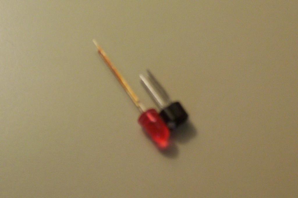
Using liquid paper (i.e. whiteout), mark the PNP transistor with a white dot. Glue the transistors back to back, and then glue the FLED onto the PNP transistor.
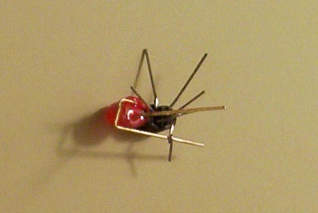
Note: The FLED’s negative cathode leg, which has the flat spot, goes to the PNP’s collector. We mixed this up the first time, and so the photographs show the FLEDs cathode bent around.
Connect the PNP’s collector to the NPN’s base. Connect the FLED’s cathode to the NPN’s emitter. Bend the PNP’s emitter straight out. Solder it all down and clip the excess leads off.
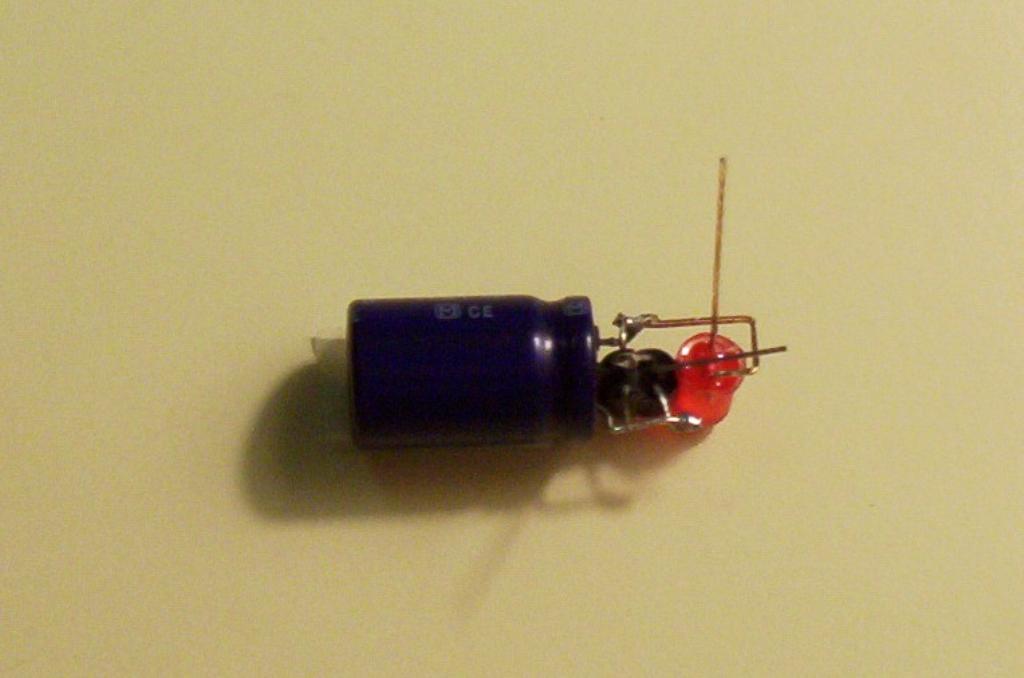
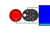
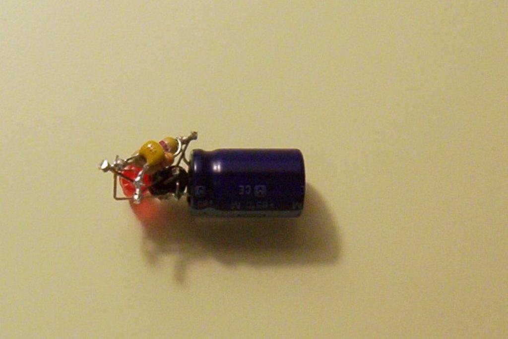
Connect the capacitor’s positive anode to the PNP’s emitter. Leave some excess in place for the positive motor mount. Solder the capacitor’s cathode to the FLED and NPN transistor.
Glue the 47 K and 3.3 K resistors together. Wrap the top of the 3.3 K resistor to the 47 K, and trim the 3.3 K’s lead off. This leaves the 47 K with the lead off the top. Wrap the .22uF capacitor around the bottom of the 47 K and the 3.3 K resistors. Solder it down and trim off the capacitors leads.
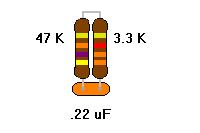
Solder the 47 K’s top lead to the NPN’s collector, and bottom lead to the FLED’s anode. Solder the 3.3 K’s bottom lead to the PNP’s base. Trim it clean, but leave some hanging off the NPN’s collector for the negative motor mount.
Duplicate this to make a second Fred solar engine.
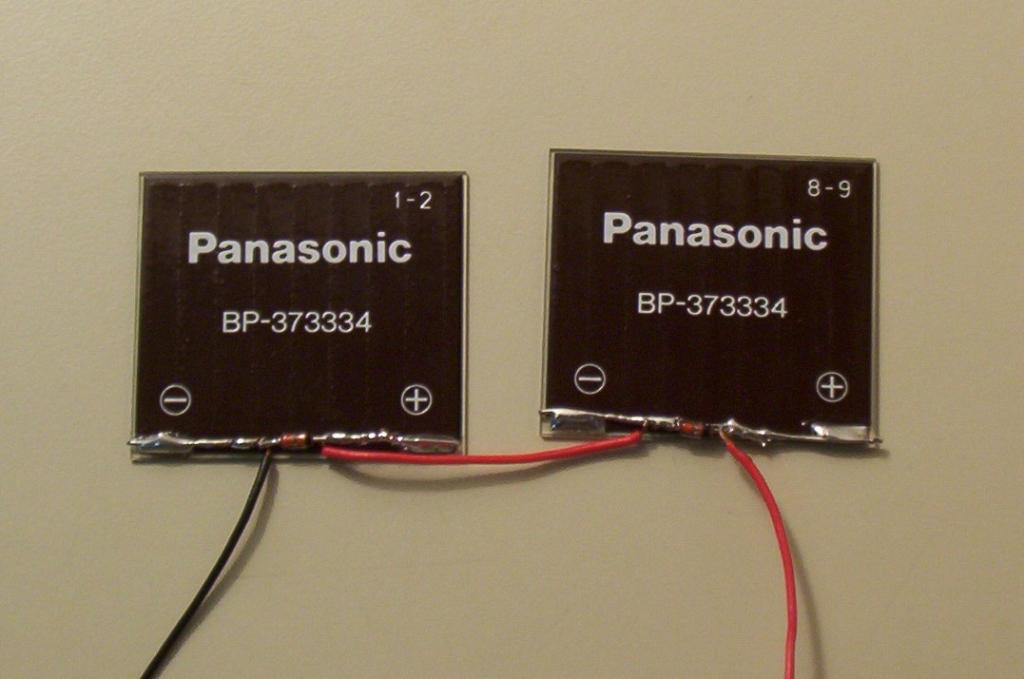
Now take the diodes and the solar cells. Solder a black wire to the positive anode of the first diode, and a red wire to the cathode. Solder this red wire from the first diode to the second diode’s anode. Solder a second piece of red wire to the second diode’s cathode.
Solder the diodes onto the BP-3733 solar cells. The orientation is opposite of what you would expect. The diode’s anode goes to the solar cells’ negative pad, and the diode’s cathode goes to the solar cell’s positive pad. Do this for both cells, wiring them in series.
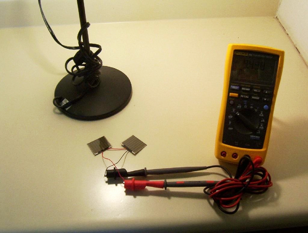
Test this under a light source to make sure you are getting the voltage. You should see slightly less than double the BP-3733’s voltage, and the same amount of current. As you move your hand across one cell or the other, the voltage will dip slightly.
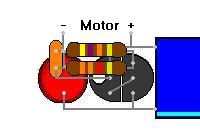
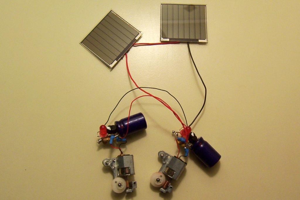
Wire the motors and solar cells to the first Fred solar engine. Providing it works, wire up the second solar engine. Providing both engines work, wire them both up and connect the capacitors of both engines in parallel (positive to positive, negative to negative). Providing everything still works, solder it down.
Use heat shrink tubing on the motor mounts. This is very important as the weight of the motors will pull at the soldering seams, and may break loose of the solar engine.
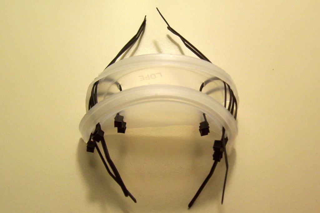
Cut a small plastic lid in half. Use an exacto knife to cut two pairs of four slits, eight slits total. These are spaced near the outside of the lid. The length of is equal to that of the wire ties. The spacing between the slits is equal to the width of the capacitor. The distance between the pair of slits is the width of the solar cell.
Thread eight wire ties thru the hole.
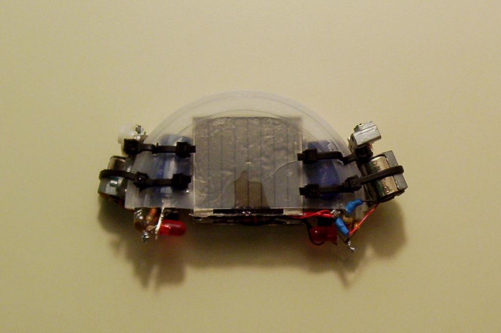
Mix up the epoxy, and prepare to cement everything in place. The cells get expoxied to the lid between the wire ties. The first set of wire ties mounts the solar engine in place. Place a spacer between the solar cells to keep them from drooping, and then tighten up the wire ties on the solar engines.
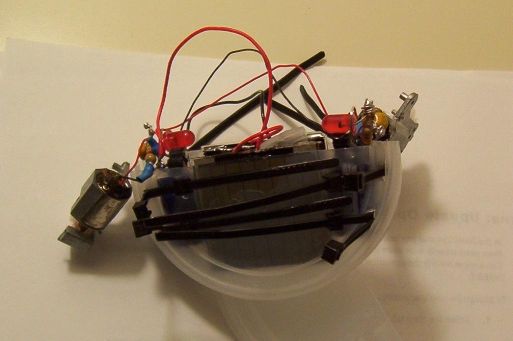
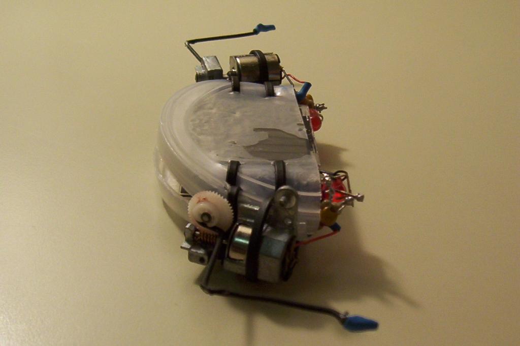
Once the epoxy is dry, put the motors into position next to the solar engines. Tighten the wire ties to keep the motors in place. Trim all the ties up.
Make the flagellum using paperclips. Add solder to one end of each flagella to create the "foot". Dip the paperclips in Plasticoat. When dry, put some heatshrink tubing on the foot for added traction ("shoes").
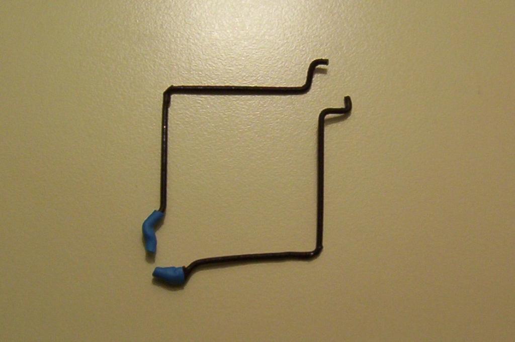
Attach the flagellum to the motors and you are good to go.