| Back to Summary |
Gather the materials, and measure out the Sintra by placing the materials on them.
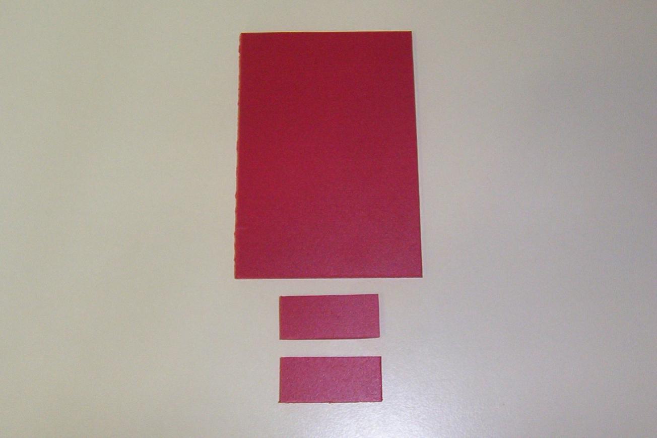
Cut the three pieces of Sintra, one for the base, and one for the left and right of the motor. My measurements were 9cm by 6cm for the base, and 1,5cm by 3cm for the motor.
Place the Sintra pieces to check the measurements. If all of the pieces line up, then sand first using 60 grit, 100 grit, 160 grit sandpaper.
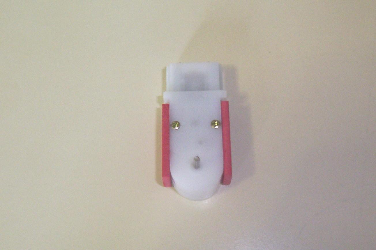
Glue the pieces of Sintra onto the motor sides.
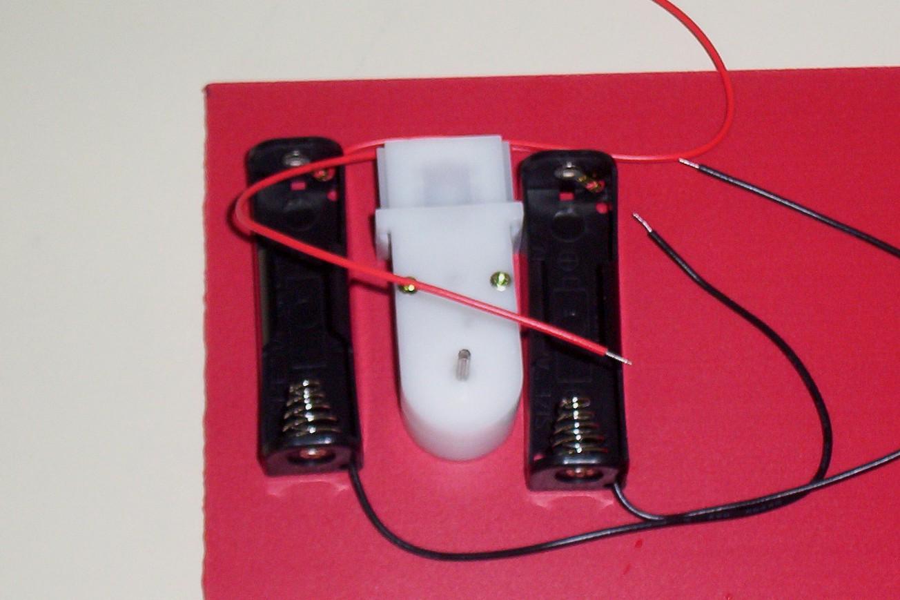
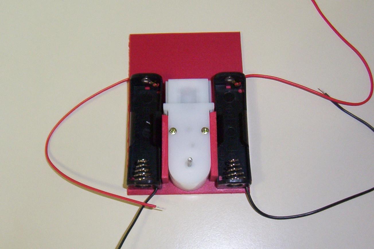
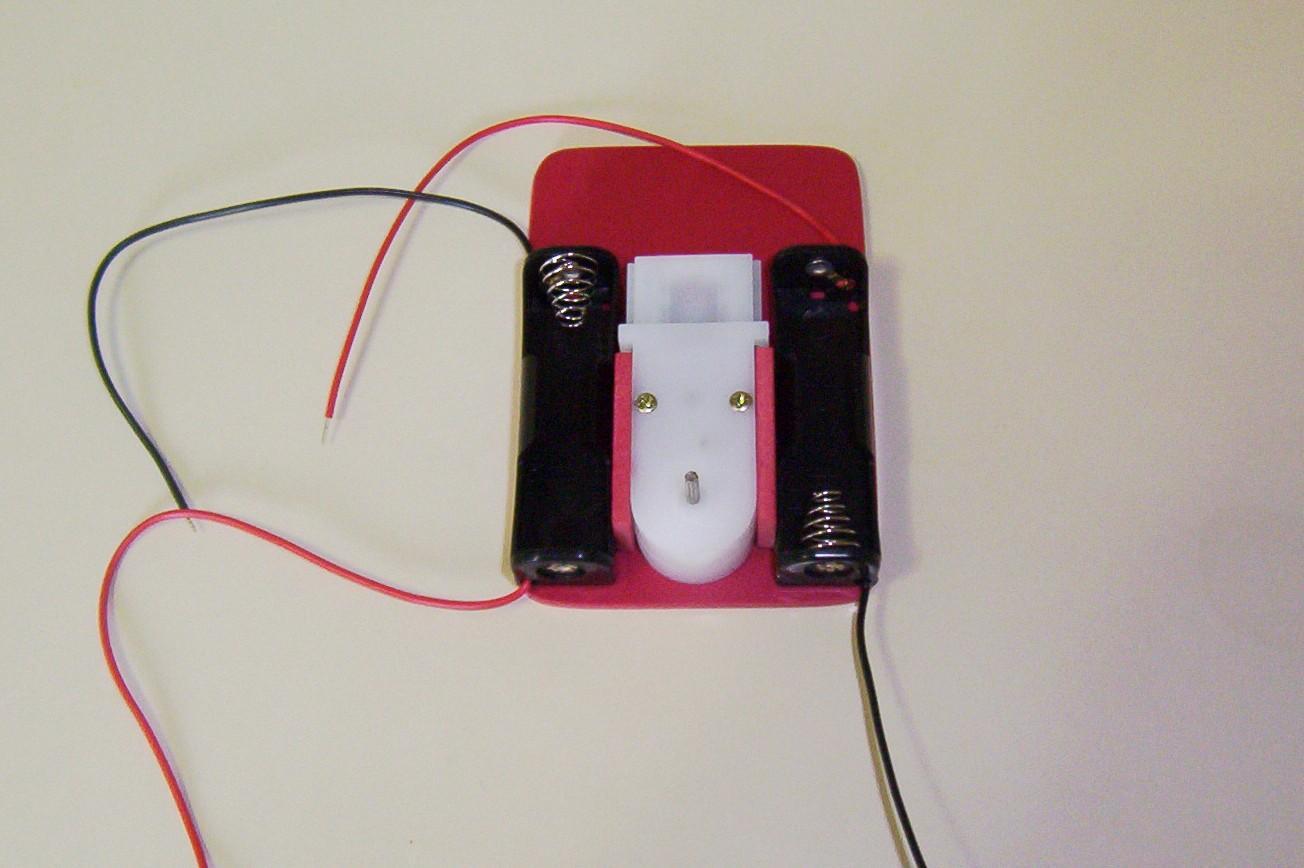
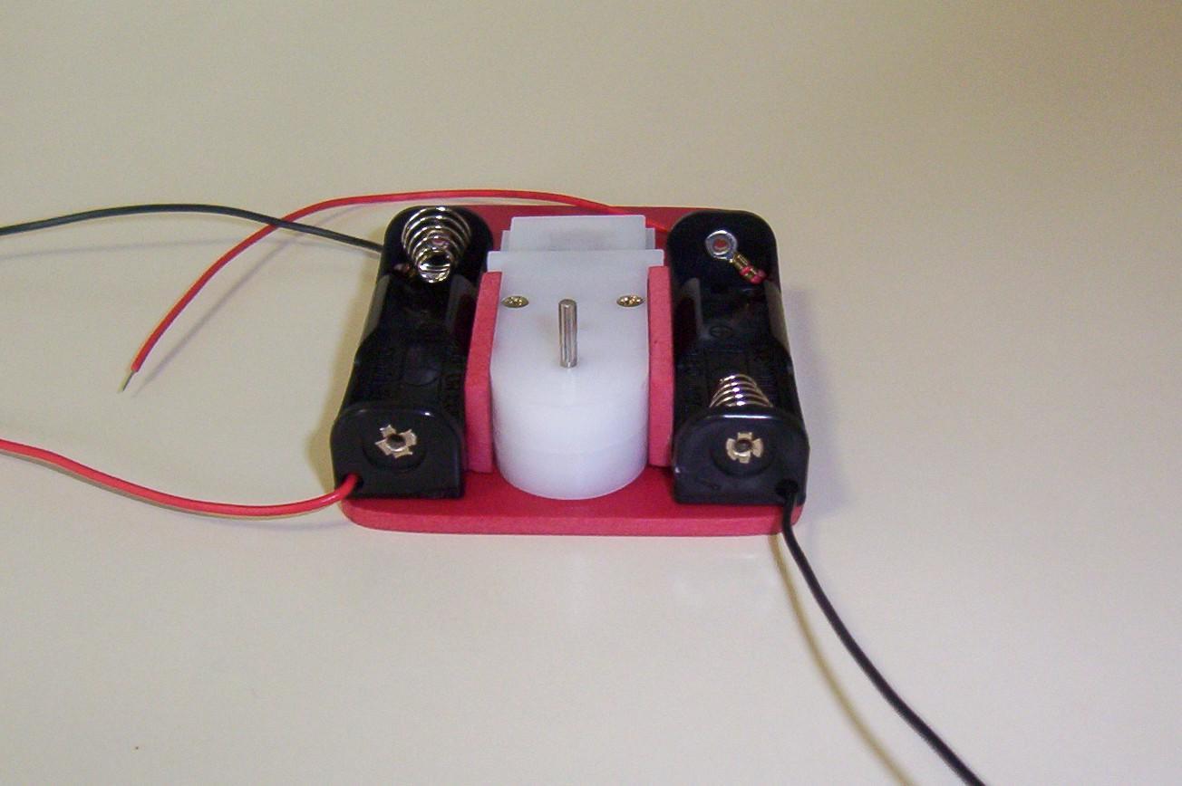
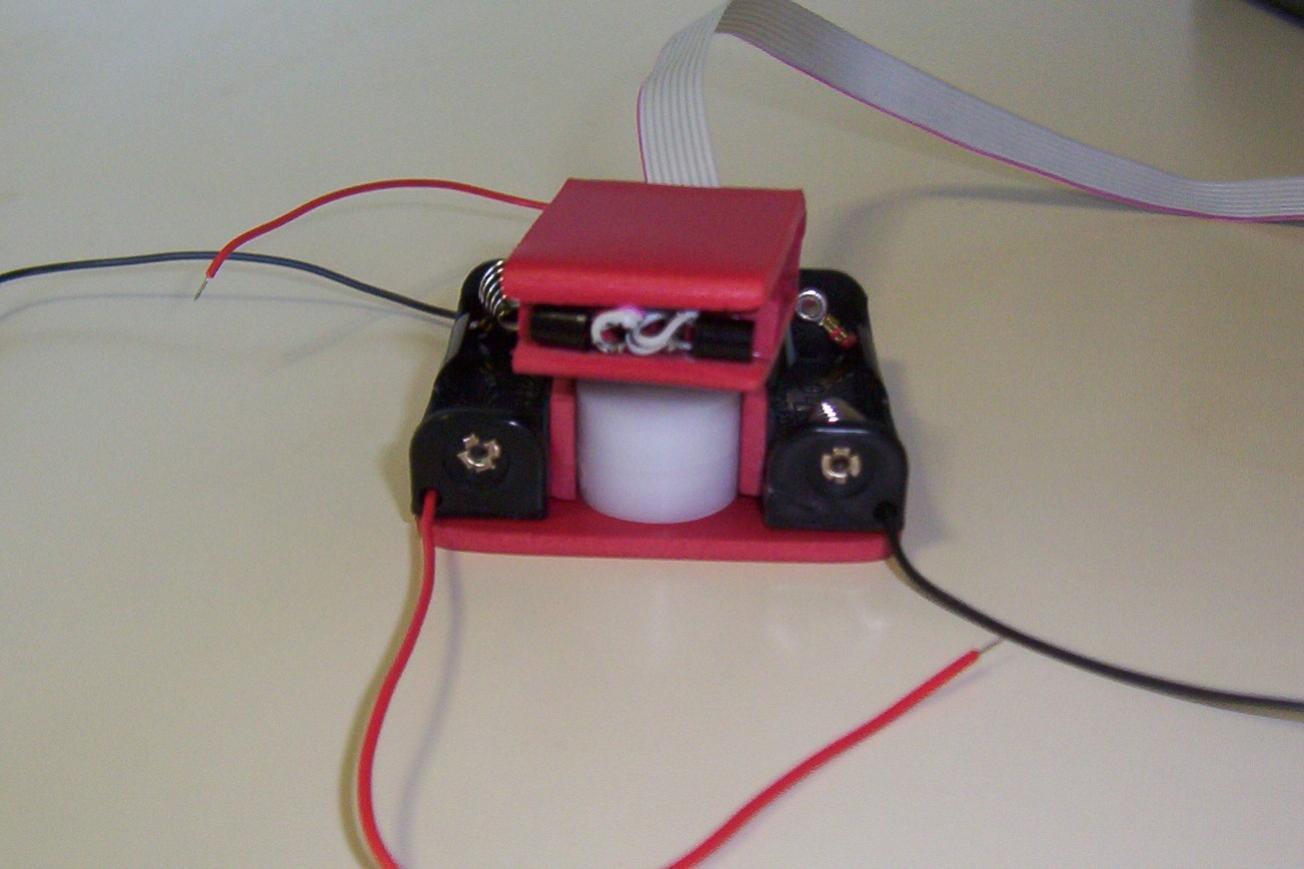
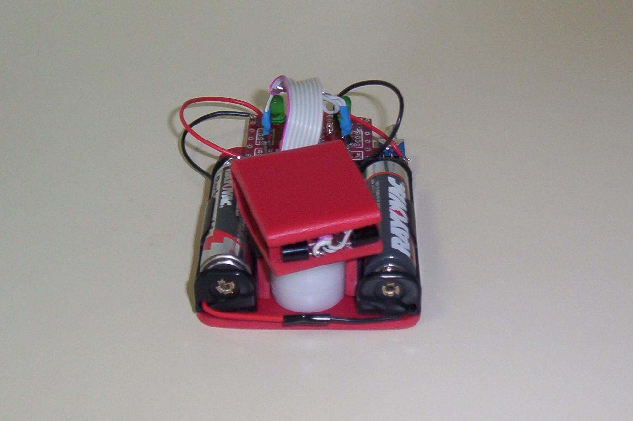
Glue the motor onto the base, then glue on the two battery holders.
Cut the head from a piece of Sintra, measuring 3cm x 11cm. Mark in lines for bending 1.5cm in from the ends.
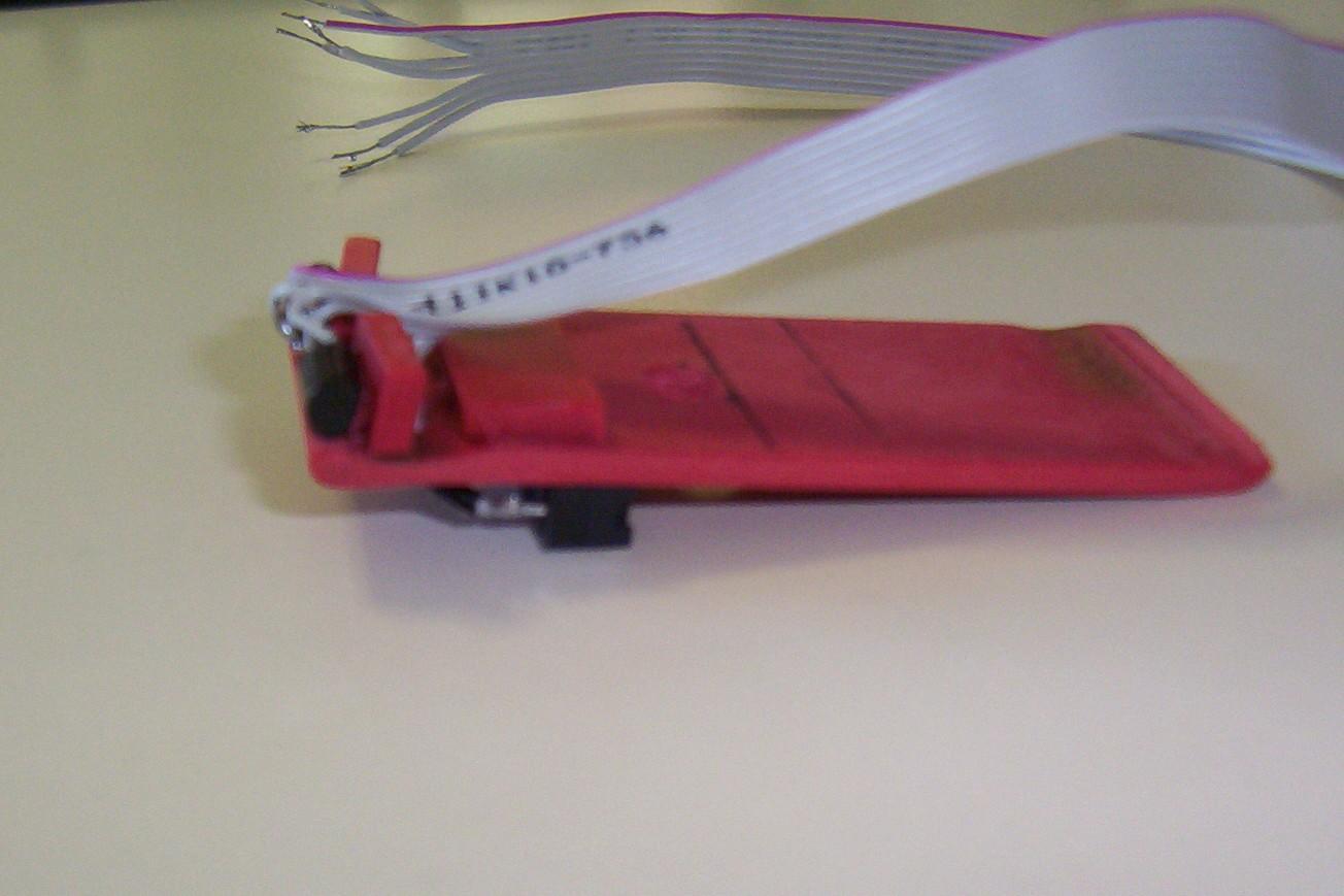
Bend the head up at a 90 degree angle 1.5cm from each end.
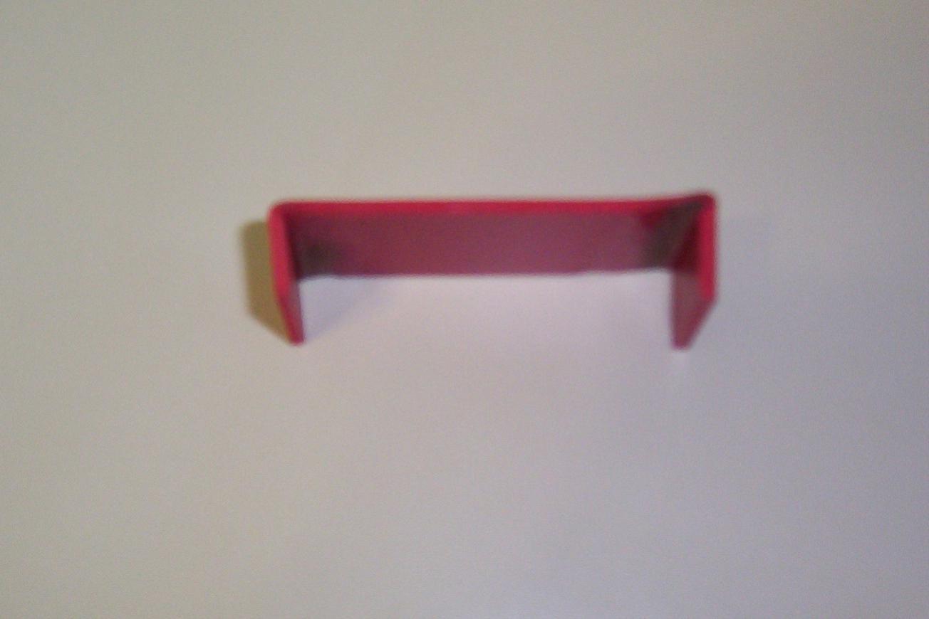
Cut these end pieces off flush with the head. This will leave a nicely curved front and rear.
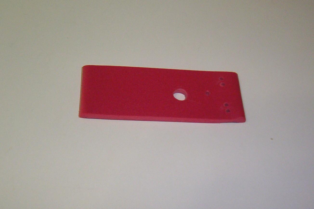
Now drill the holes for the motor, the limit switches, and the spinal cable. When complete, the head will have approximately 3cm x 3cm for the top and bottom, and 1cm x 3cm for the bend. Position the 5/64" hole for the motor at 1.5cm x 1.5cm, which centers it on the bottom. Position the 1/4" hole for the spinal cord at 1.5cm x 2.5cm, which centers it and places it at the absolute rear of the bottom. Drill the 5/64" holes for the limit switches at 5mm from the end, equally spaced. Sand the head as you did the base.
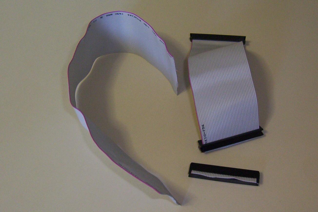
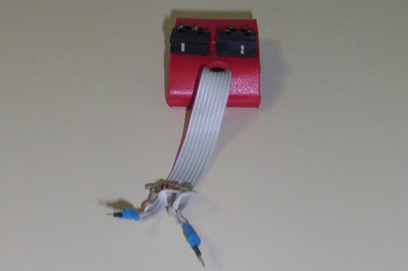
Cut the spinal cord from a hard drive, floppy drive, or other ribbon cable. You will need 8 wires: two for each photo diode, and two for each limit switch. The length of the spinal cord is 15cm. This is roughly twice as long as you will need to go to the Bicore. You will want it that long so as to comfortably reach the breadboard.
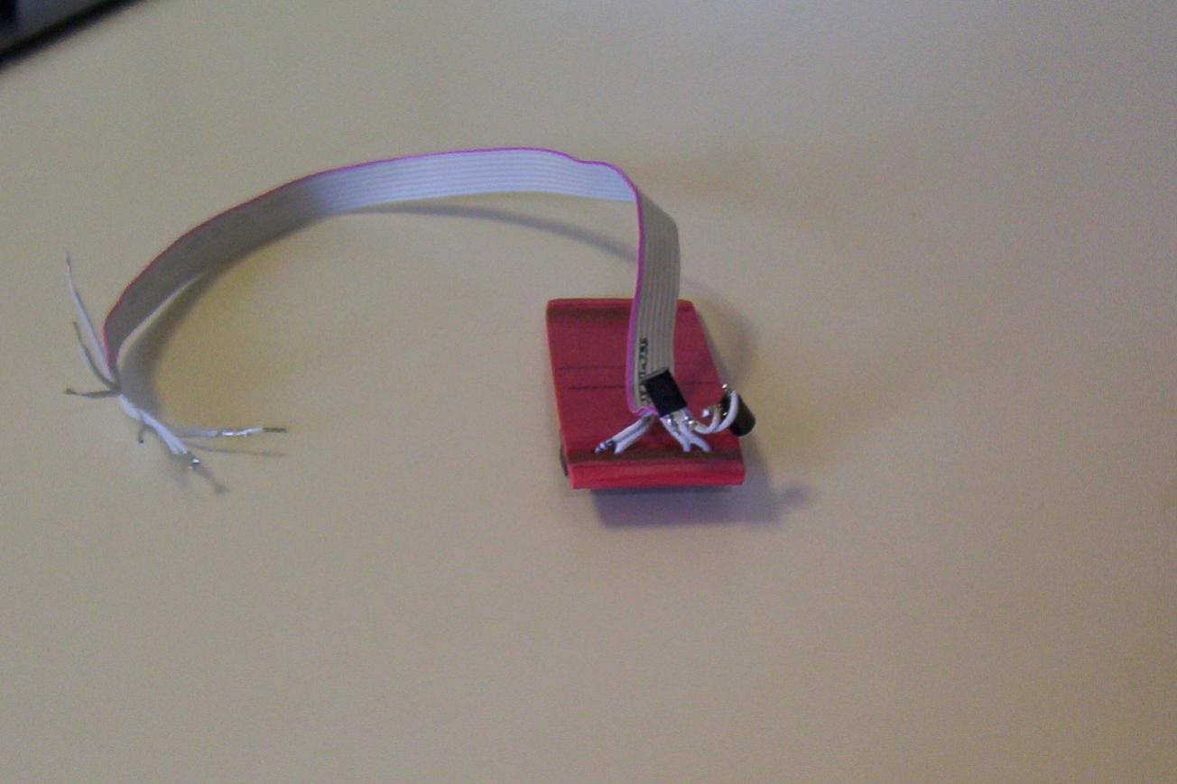
Solder the spinal cord to the photo diodes (PD) and limit switches. The cable pinout going from colored cable out is: left PD cathode, left PD anode, left switch in, left switch out, right switch in, right switch out, right PD cathode, right PD anode.
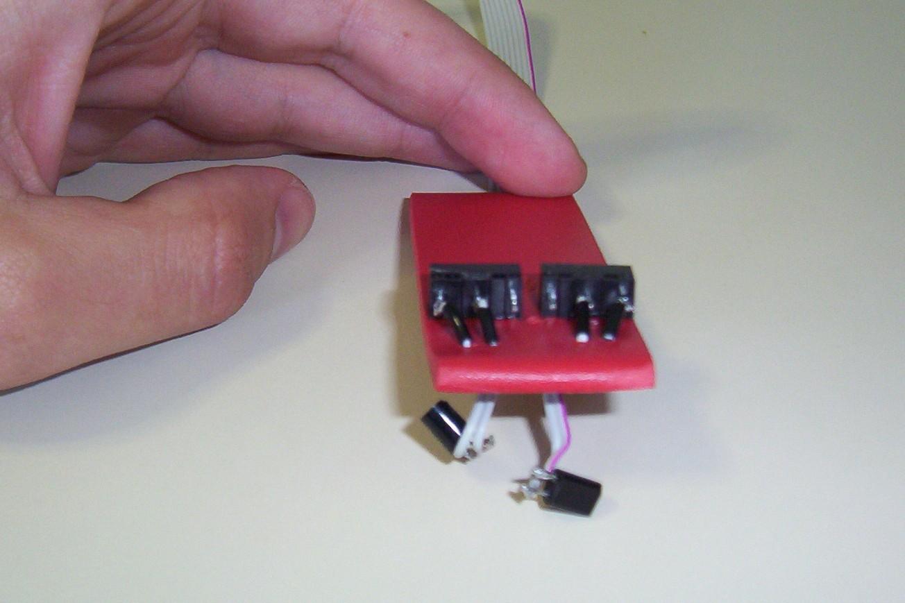
Cut two sections of Sintra and glue the PDs to them. Cut another 1cm x 2.5cm piece of Sintra and glue this over the motor hole. This acts to stop the motor's axel from going to far. Glue the limit switches into place so that the switch is slighly behind the motor hole.
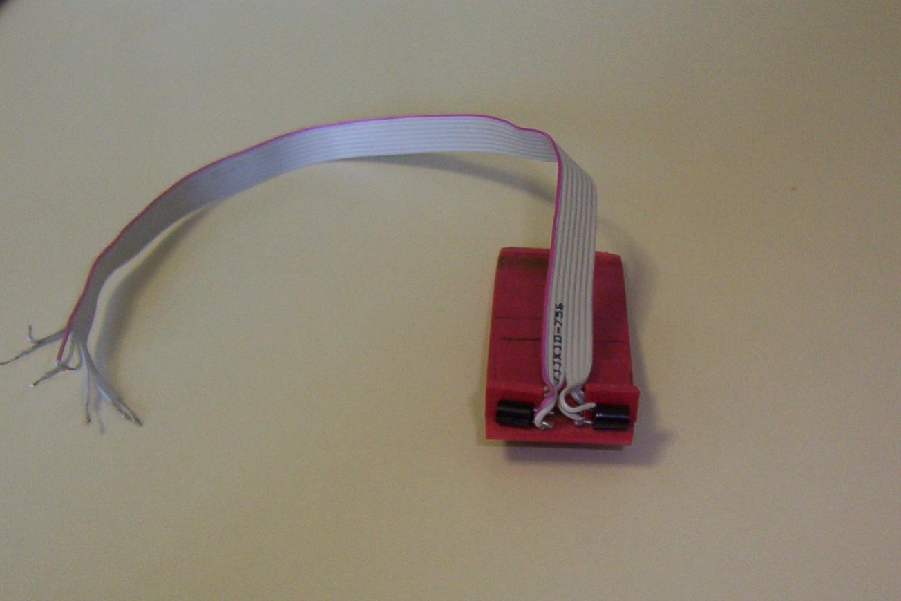
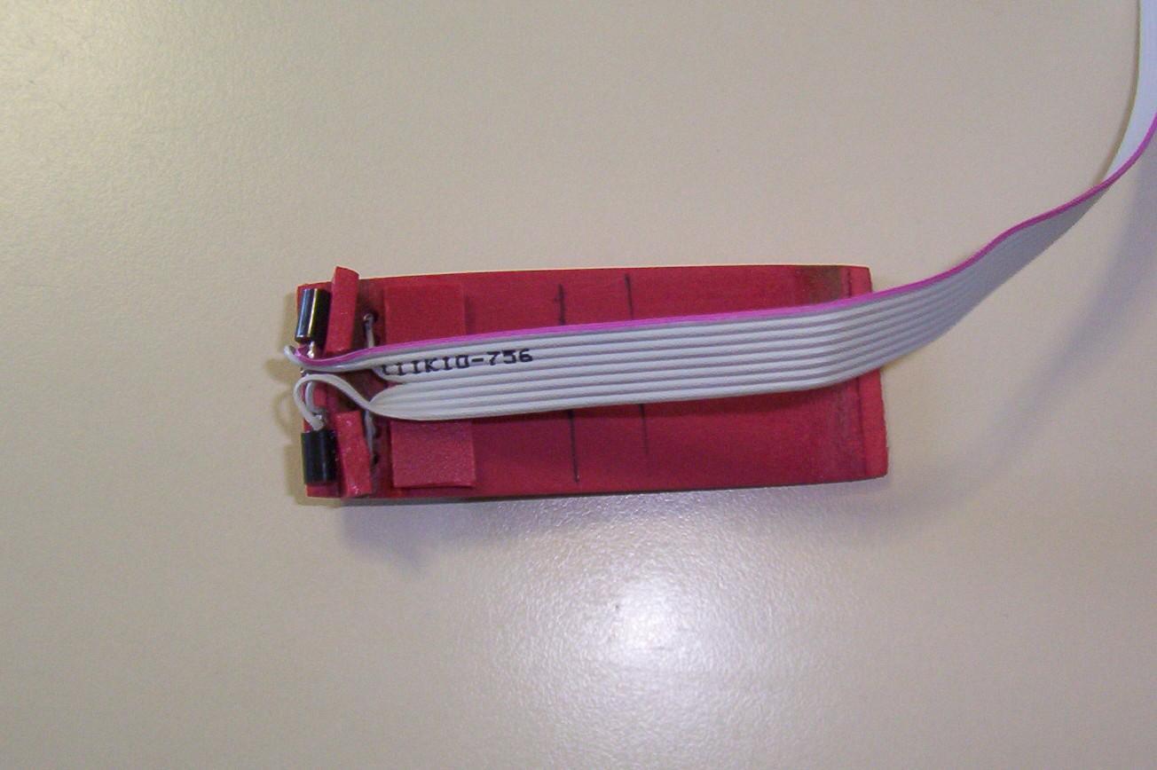
Feed the spinal cord out of its hole. Hold it out of the way using a pair of pliers or vice grips. Heat the Sintra near the back and bend the top over onto the bottom. Glue onto the piece of Sintra holding the PDs.
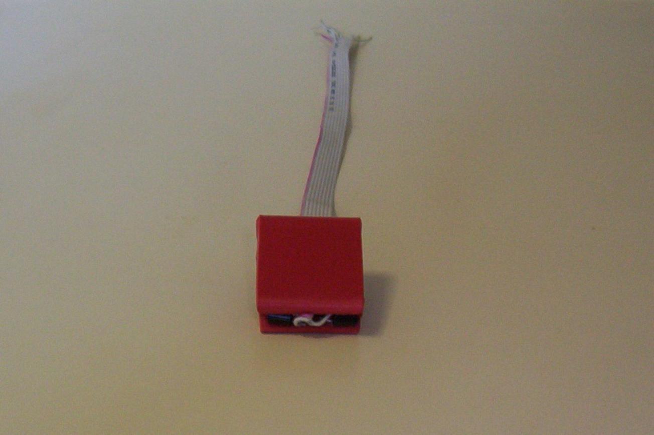
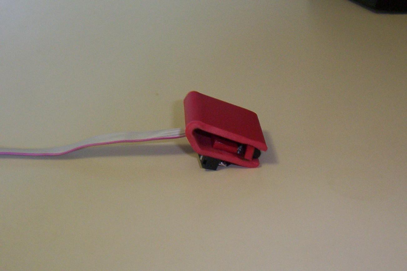
Place the head onto the motor mount, but do not glue it on yet. You will want to be able to remove it later when you tweak the positioning of the stop and the limit switches.
Assemble and test the Bicore circuit on the breadboard. Use a pair of needlenose plyers to click the limit switches. One variable to test with is the resistor in between the PDs, going from no resistor up to 1M. Once you have it working properly, then proceed.
Cut the spinal cord so that it measures 8cm from where it exits the head to the end of the cord. Solder the PDs, limit switches, and resistor as shown below.
Solder the battery pack to a switch, and glue the switch onto the base. Then assemble the circuit on the BEP BC2 board. Solder in sockets at I1 and I2. The two pins from the spinal column plug into these two sockets.
Alernatively, you can free-form the circuit using the directions found in the Bicore Head project in the Junkbots, Bugbots, and Bots on Wheels book.
Now is the time to experiment with the stop plate by cutting out the Sintra, and holding it in place with scotch tape. The stop plate has two functions. First, it triggers the limit switches when the head has turned too far. Second, it serves to support the spinal cord. The ideal stop plate is narrow as that allows for a wider degree of motion.
Below is a failed stop plate. This stop plate was a rectangle and measured 7mm x 14mm. The problem with this stop plate was that the flat casing on the limit switches struck the plate before the switches triggered, causing a mechanical stop but not causing the Bicore to reverse.
We had the best success with a 2cm x 2.5cm cut at a 45 degree angle. We tested this shape by taping the stop plate in place, connecting the spinal column to the Bicore circuit, placing the robot in a semi-dark room to ensure a wide degree of motion, and letting the robot run its batteries down. The limit switches make an audible click when triggered, and in the dark the head turns all the way to one side, clicks, then all the way to the other side, clicks, and the back.
Shape and sand the stop plate, and glue it onto the motor. Put the head back in place, and again test the functionality to ensure the limit switches are clicking properly. Once you are done testing, glue the head into place. Cut a section of Sintra to support the Bicore, and glue the Bicore and Sintra into place in the rear of the base. You are done after the glue dries.
1) Eye placement. The Head Boy roughly tracks light due to the placement of the PDs. A better solution would be to have them out at a 45 degree angle, and perhaps give them an eye shield akin to the heat shrink around the Fred's FLEDs.
2) Eye's Resistor. The resistor in between the PDs is used to ensure that the Bicore can spin the entire field of view. If we build this type of head again, we would consider using a 10-turn trimpot to allow for more tweaking.
3) Spinal Cord. Originally, we did not know how many of the wires we would need. Advice and experimenting showed that we realistically only needed two cables, one for each input on the Bicore. It may have been better to place the resistor inside the head, and feed out only two wires.
4) Limit switches. The large surface area on the mouse switches prevented the switch from being triggered with smaller stop plates. As a larger stop plate means a smaller range of motion, it would be better to use different switches, or position the switches so that the switch itself is closer to the motor shaft.
5) Glue. As the head's motion tends to pull and push at the Bicore circuit, we thought using the white hobby glue would be best as it allows for a flexible joint. This is the same glue we used for the Twin Mills photovore. Unfortunately, this glue is water based leading the Bicore to blink wildly until it dried a couple of days later. Also, the glue did not hold up to the head's motion. In the end, we went with two-part epoxy.