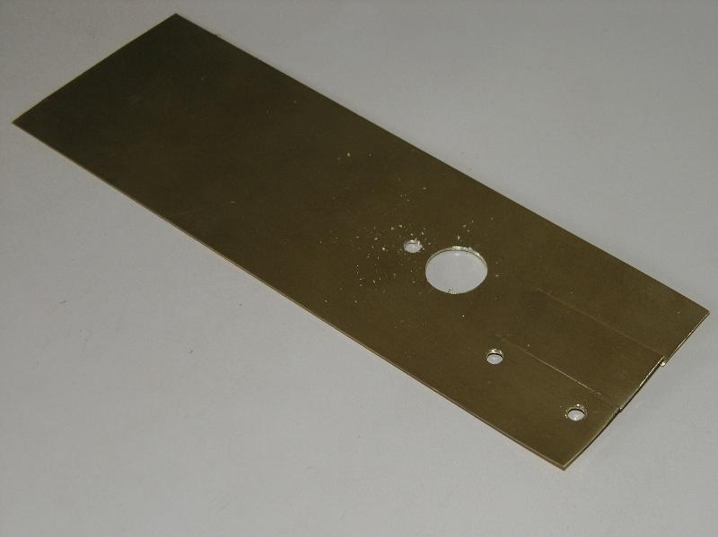
Print the brass template.
Brass Template
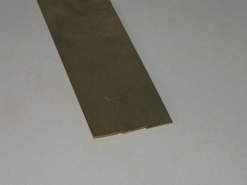
Cut two slits (2.7 cm) for the rear fender.
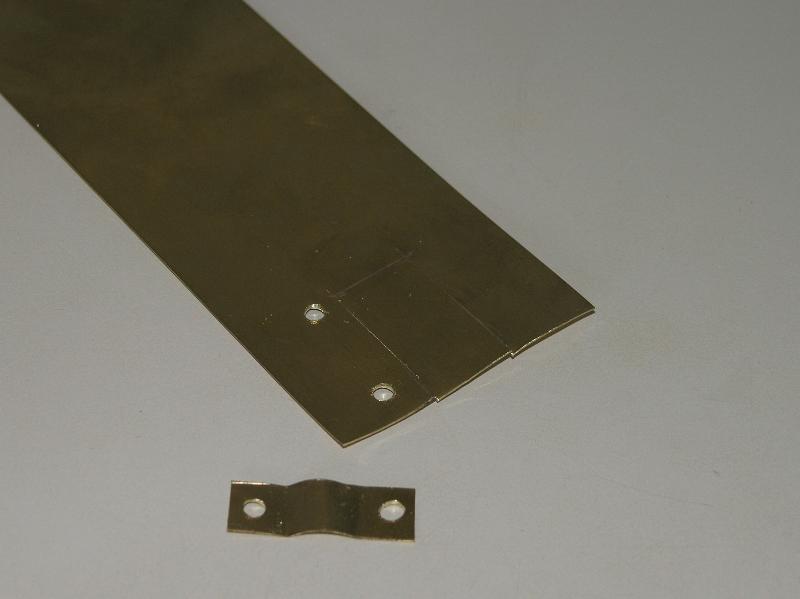
Drill two 1/8" holes for mounting the rear drive motor. Make an accompanying bracket from spare brass.
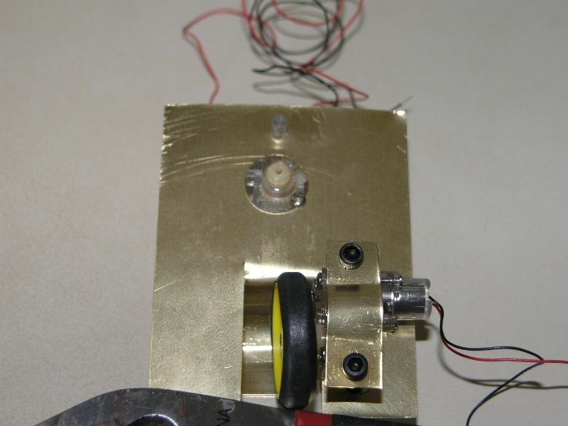
Drill the 1/2" hole for the steering motor.
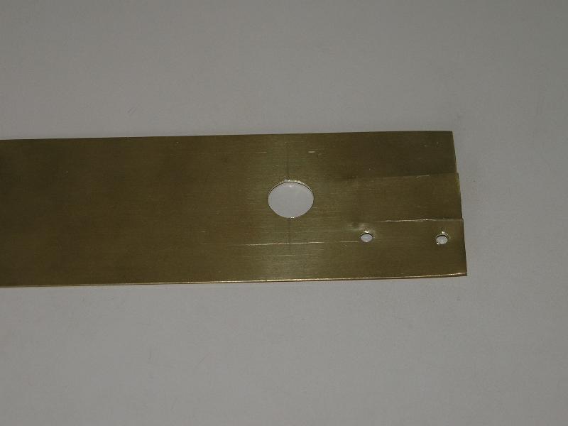
Drill a 1/8" hole. The tab on the GM10 will fit into this.
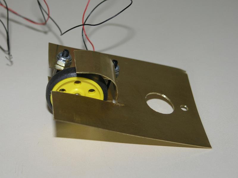
Attach the GM10 wheel to the drive motor. Shape the rear fender. Use 4-40 bolt and lock-nut to secure the GM10 into place.
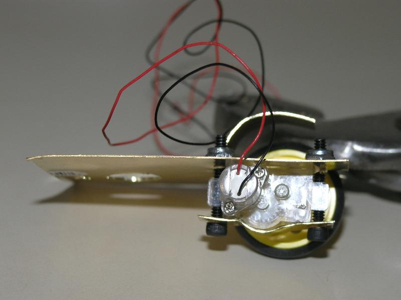
Grab the steering motor. There are two screws on the GM10 near the motor shaft. Loosen the one on the same side as the tab. Slide the motor into the 1/2" shaft hole and 1/8" tab hole. Tighten the screw. Take care not too over tighten!
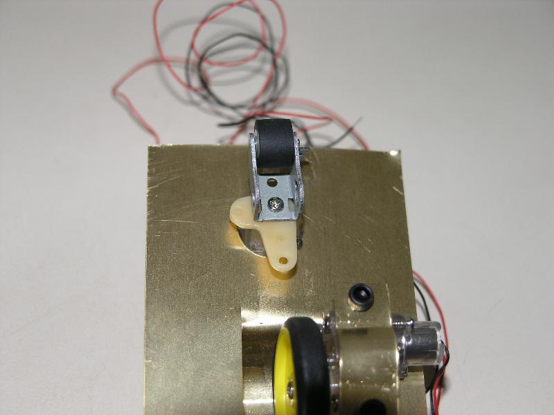
The pinch roller serves as the front wheel. Screw the pinch roller onto the steering motor.
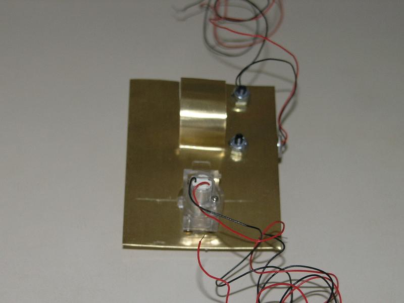
Bend the front on about a 60-degree angle. Cut parallel with the ground (this serves as a skid pad and should not be more than 2 mm from the ground). Cut the back on a matching angle.
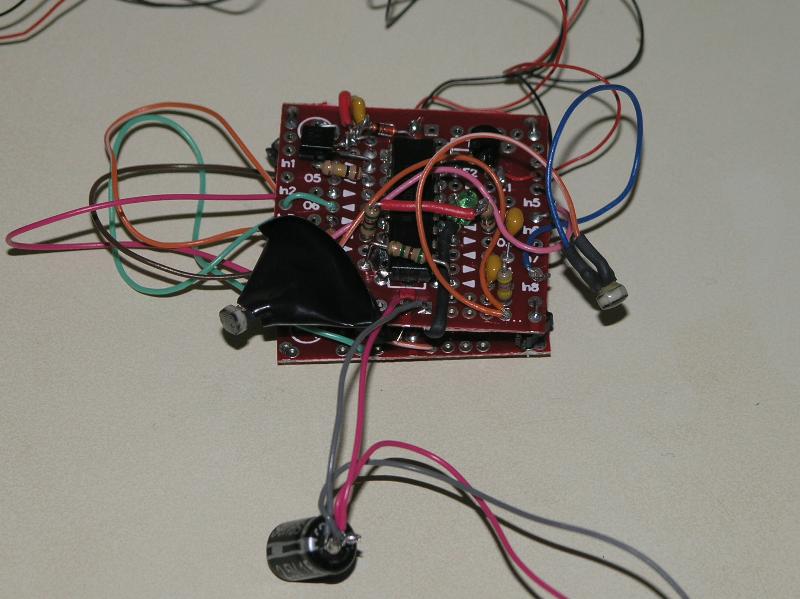
Follow these directions to populate the BC1 and MD2 BEP boards. Add a 1K resistor to the PN2907 base, wire the PN2907 emitter to Vcc, collector to the drive motor. Wire the second drive motor to Gnd.
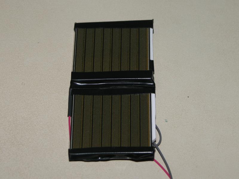
Wire the two Panasonic BP-3733s in parallel, connect to the 1F Super capacitor by means of a switch. Place the cells on a piece of Sintra for backing.
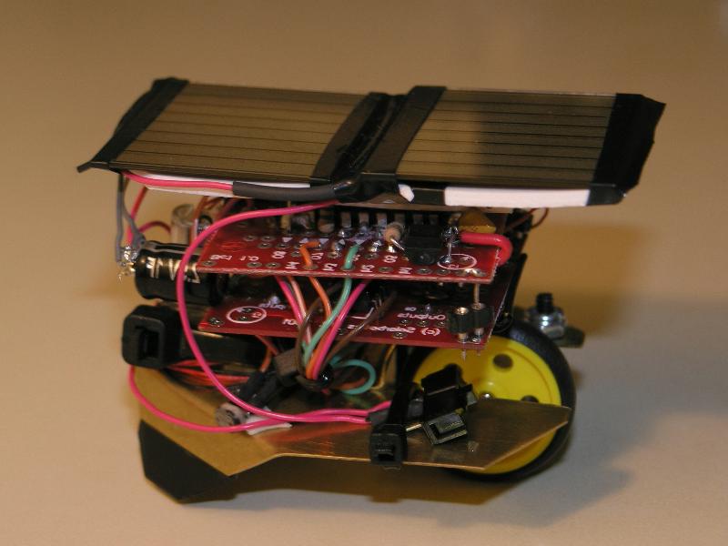
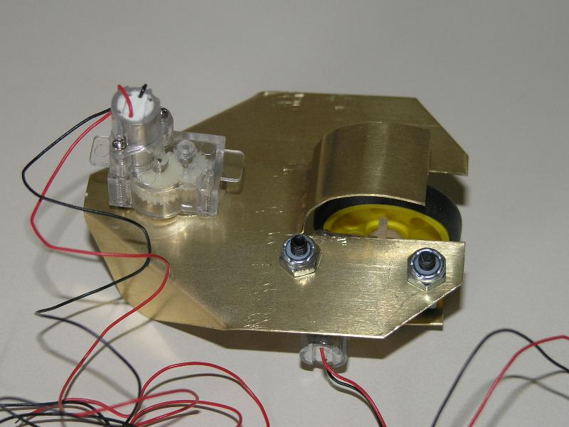
Put it all together. Glue the solar panel sintra to the BC1 IC. Use wire-ties to straighten up the wires.
Attach the circuit board by means of sticky tape. The front rests on the steering motor, the rear rests on the fender.
Done!