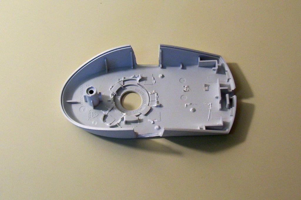
Remove the mouse cover, and gut the mouse by removing all plastic stands from the bottom. Glue the mouse ball shield in place. Cut along the ribs to form an entry point for the motors. Sand the bottom and the cuts smooth.

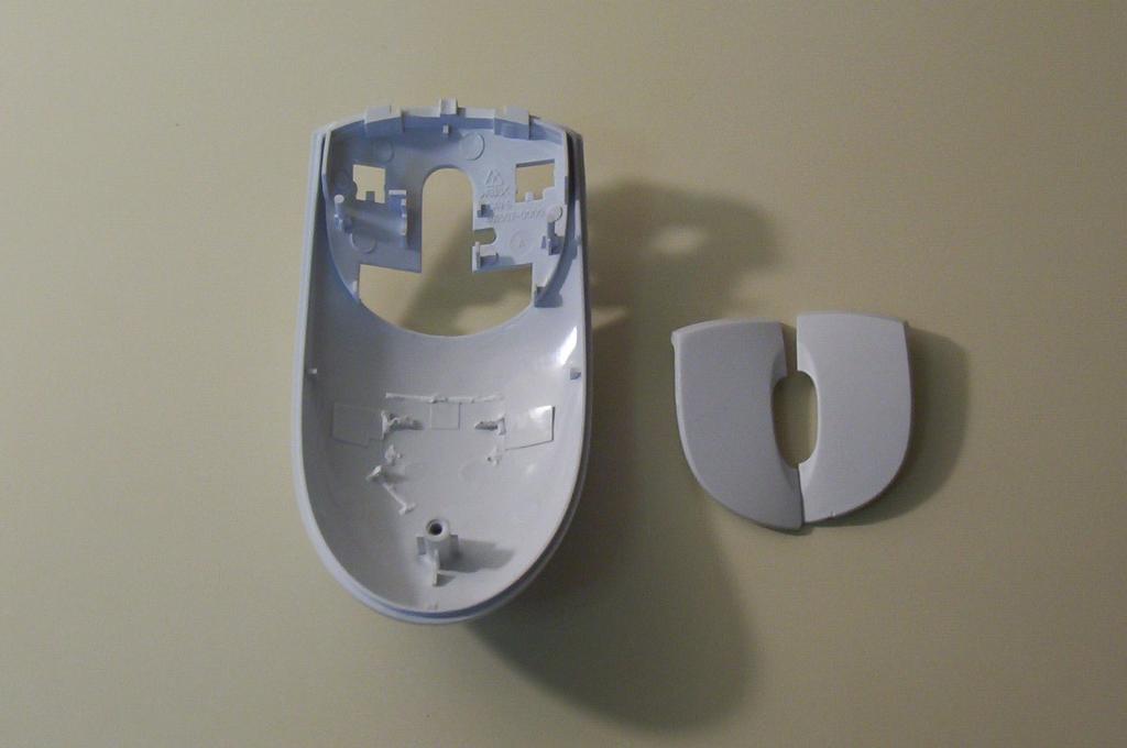
Remove all plastic stands from the top, including the mouse buttons. Sand the top smooth. Seperate the mouse buttons.
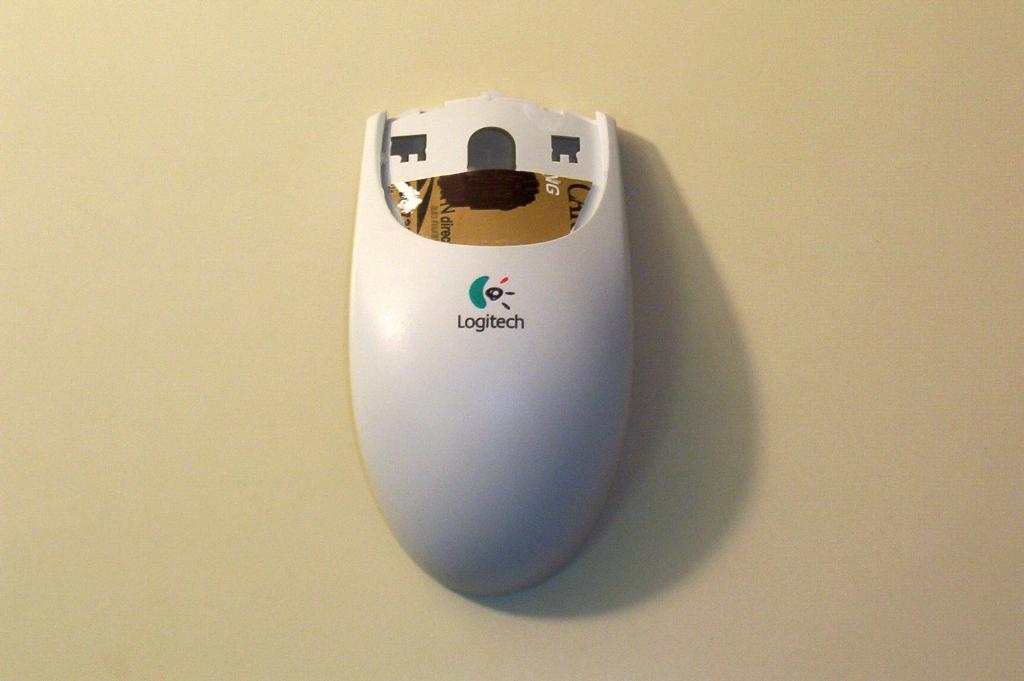
The next step requires a thin piece of plastic. Use a sample card that credit card companies send out in their mass mailings.
Cut the card to form a piece of plastic that reaches roughly half way into the mouse scroll wheel hole.

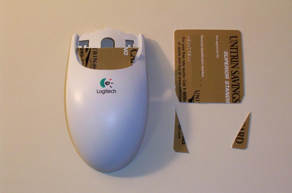
Glue this piece of plastic into place. Darken the plastic with a sharpe or other marker.
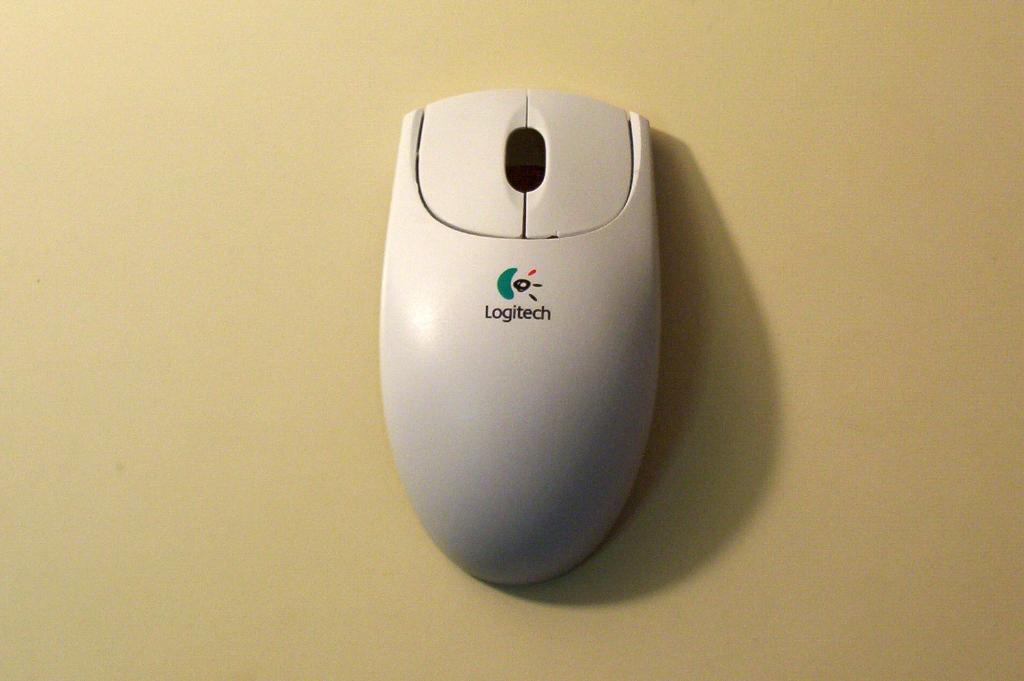
Glue the mouse buttons into place over top this piece of plastic.
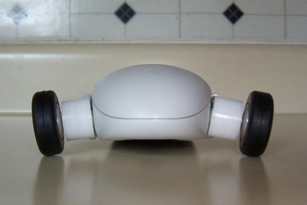
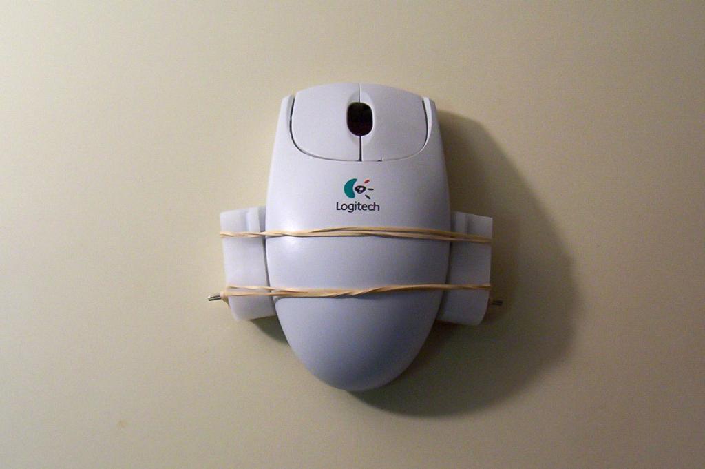
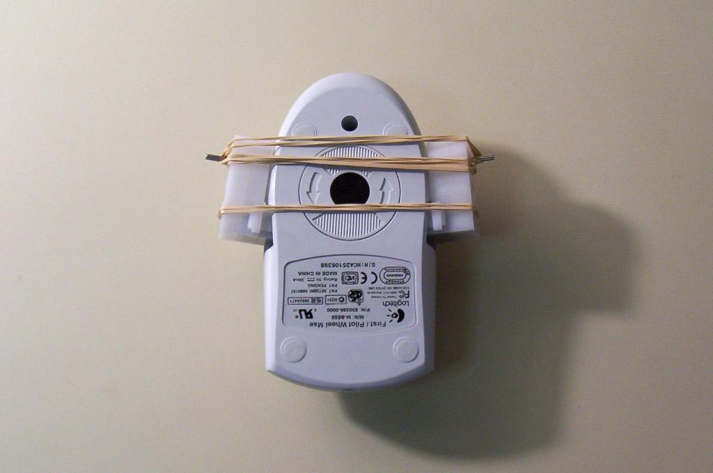
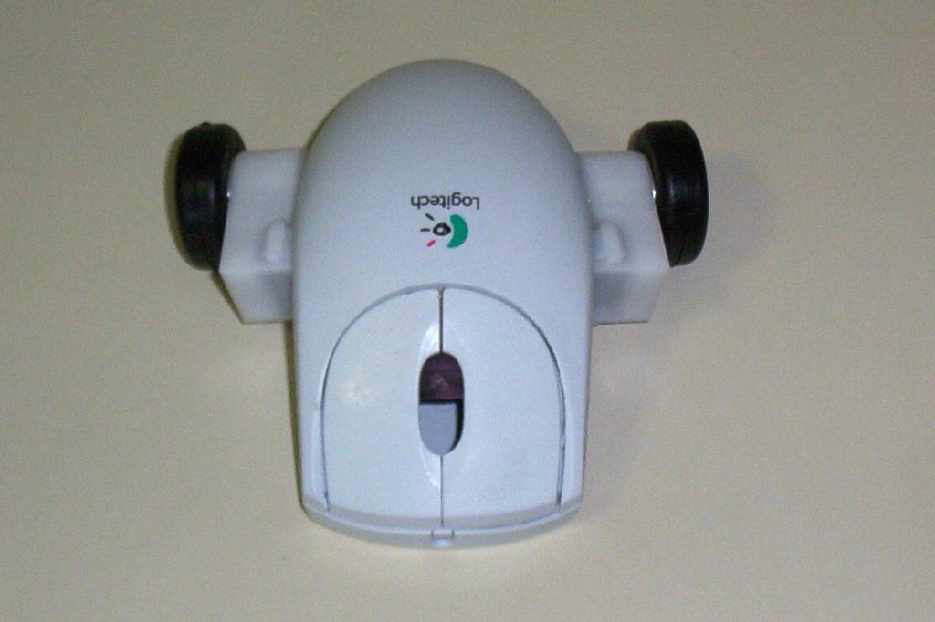
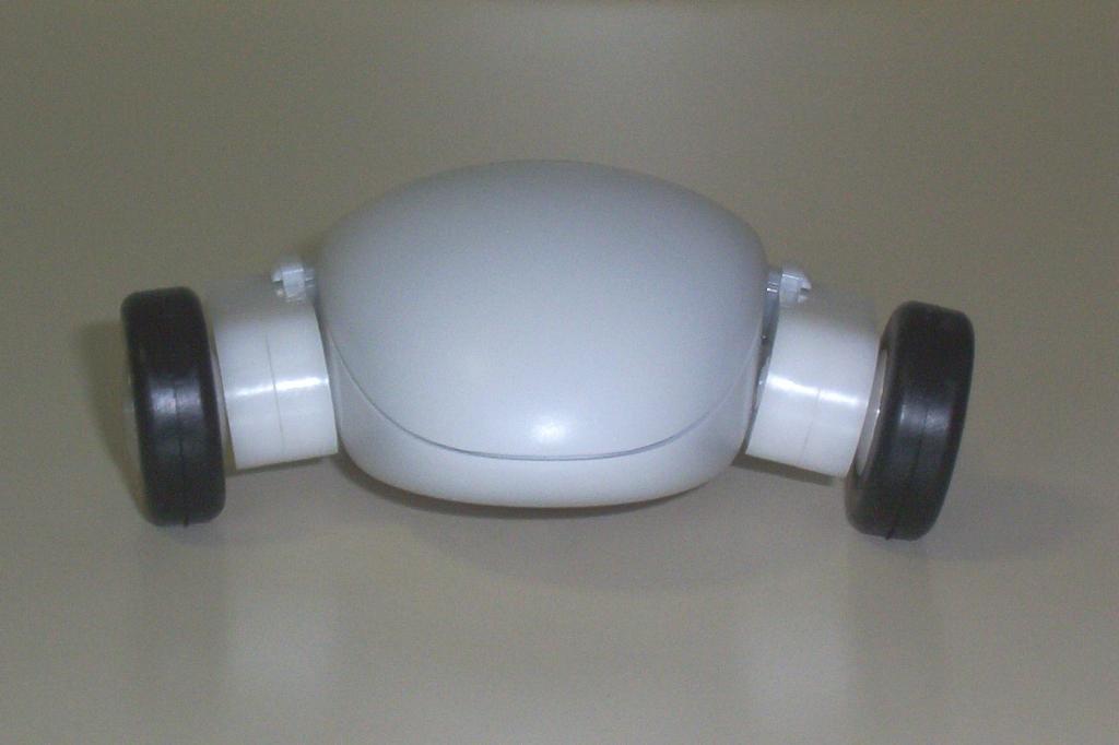
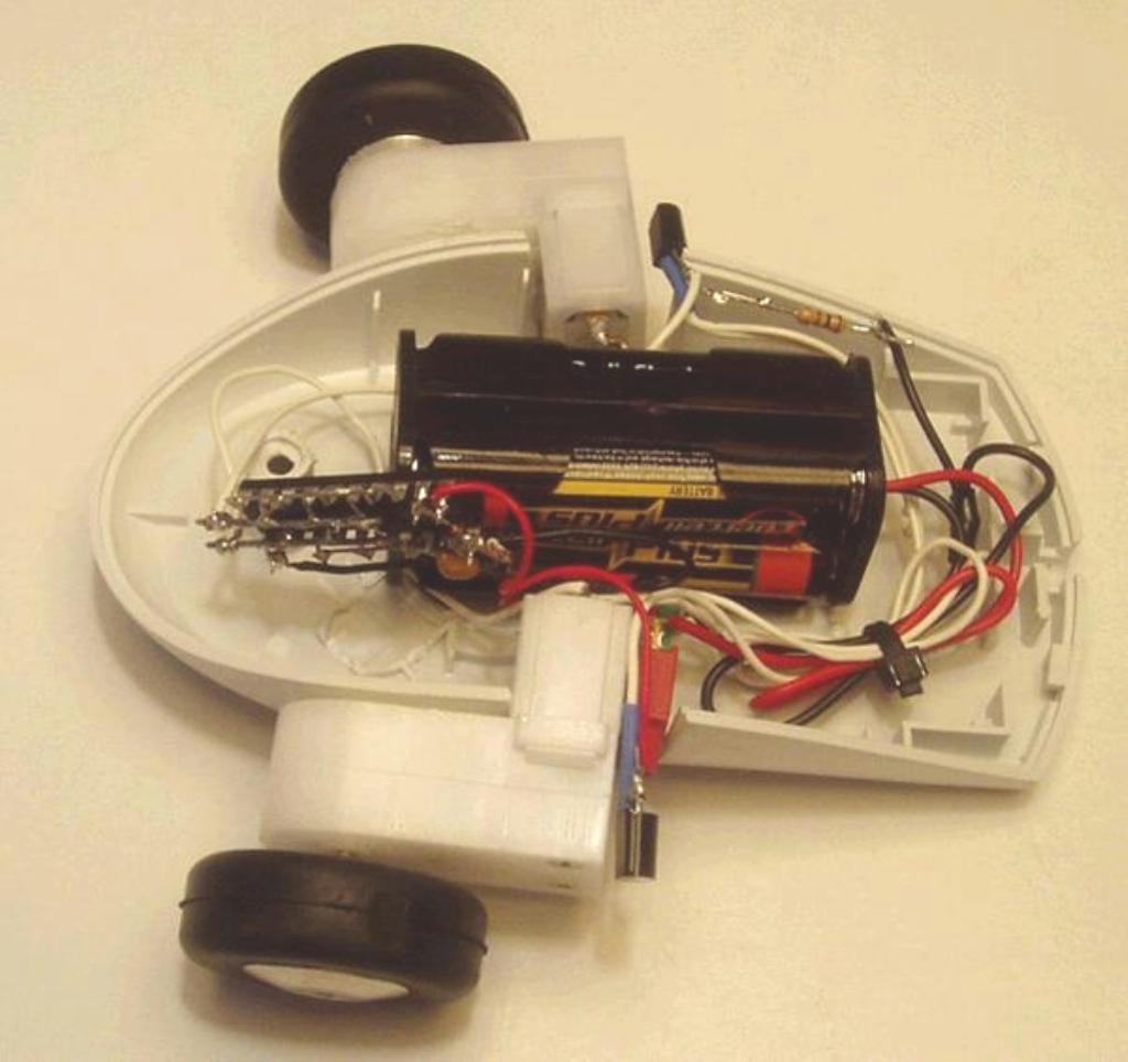
Put the motors in place, and screw the mouse cover back on. Use epoxy to glue the motors in place. Use three rubber bands to hold the motors steady while the epoxy sets: two bands on to hold the motor casings, and one band to hold the shafts to ensure alignment.
Allow the epoxy 24 hours to set, then glue on the wheels.
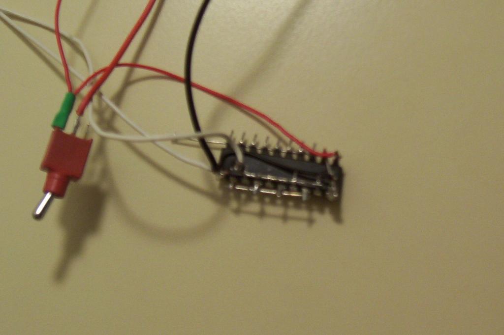
Place the mouse body on a raised surface, such as a tape cassette case. This allows the wheels to turn without the robot moving. Breadboard the circuit and test it out. Free-form the circuit once it is working on the breadboard.
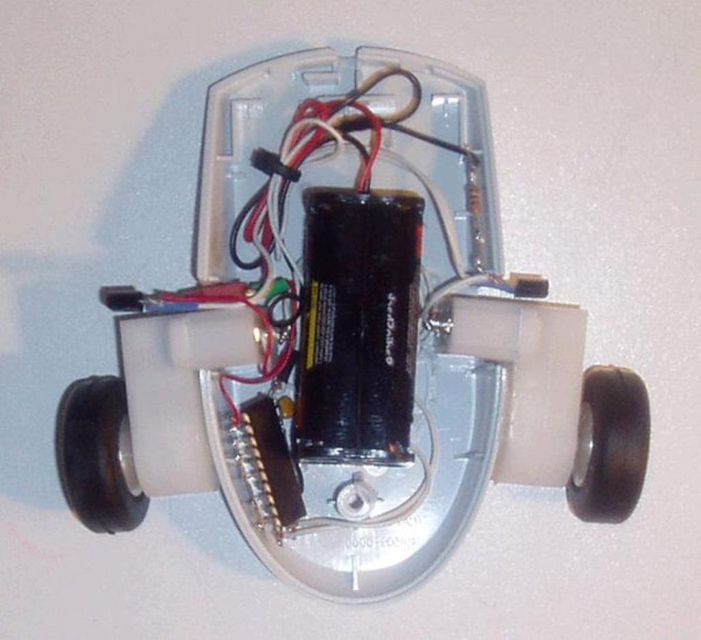
Install the circuit behind the mouse screw stand. Install the battery pack in front of the stand, in between the motors. The mouse cover's dome holds the battery pack in place, and the screw stand helps to ensure that the pack will not short out or smash the free-formed chip.
Test it all out. Providing everything works, you are good to go!