Use 3mm white Sintra to prototype the robot. We go thru a couple rounds of doing it by hand, measuring, drafting the design, cutting from the draft, and then refining and re-measuring.
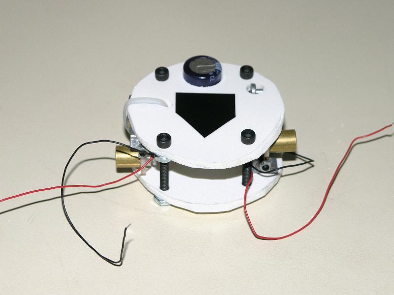
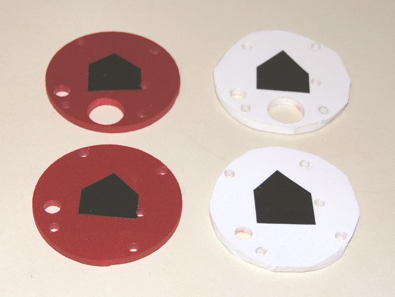
Create and print a Sintra template.
Sintra Template
Once complete, we cut out the final robot from 3mm red Sintra. Use black electrical tape to keep track of which side is out and which way is front.
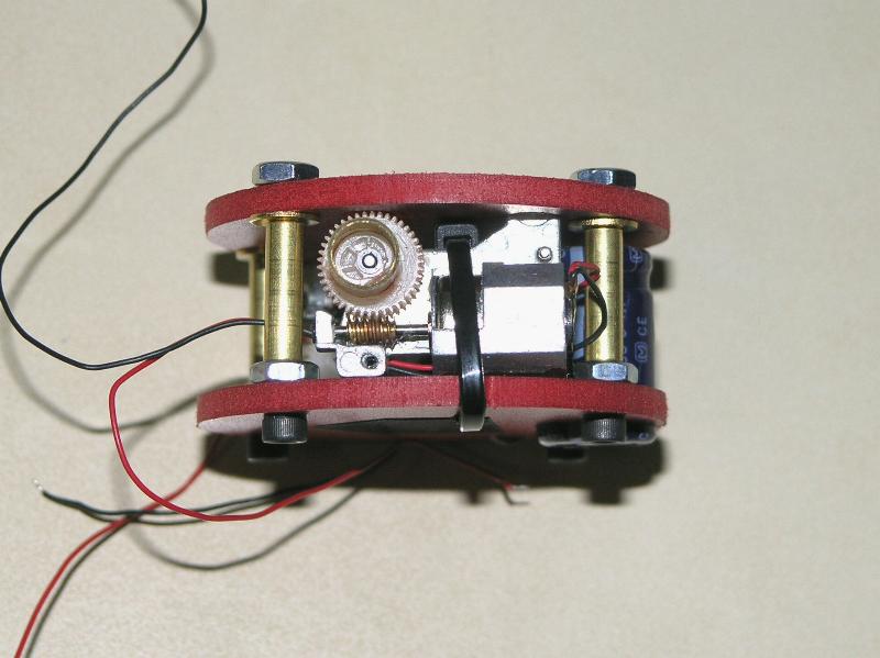
Mount the motors using wire-ties. By press fitting, find and mark the spot where gear motor touches the Sintra. Scuff out this spot with a Dremel.
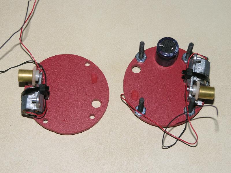
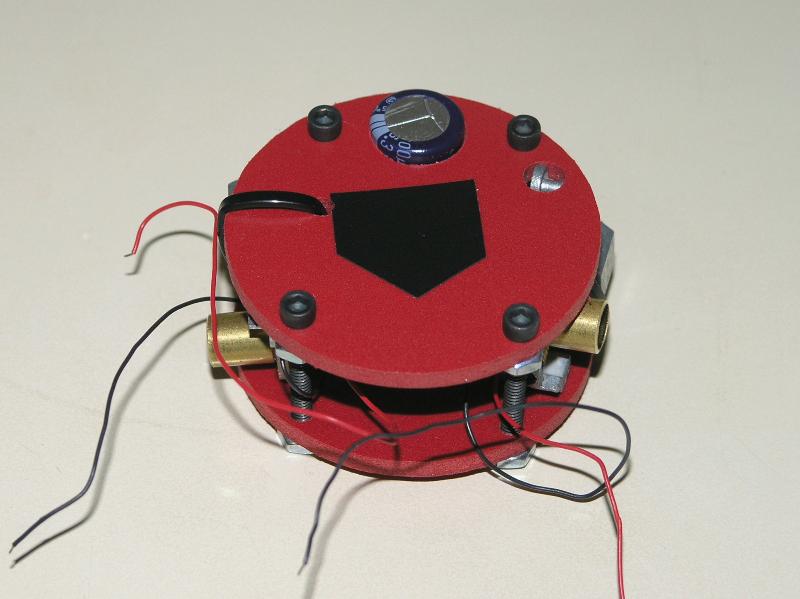
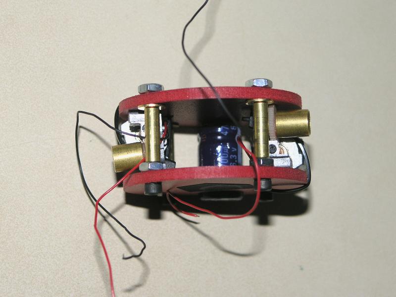
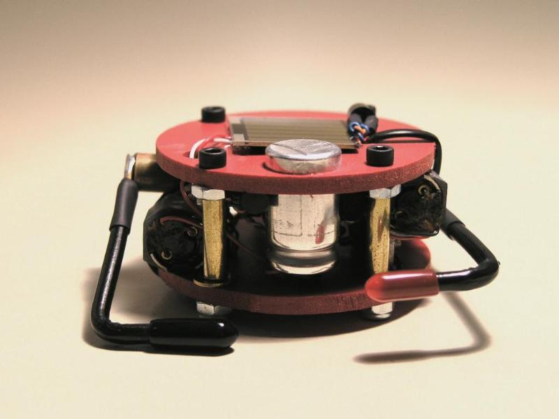
Assemble the robot. Drive the motors with a 3V battery, making certain that the gear motors can spin freely.
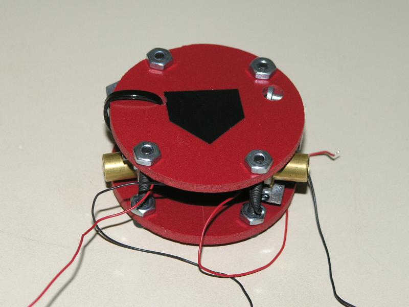
Cut brass spacers from a 5/32" brass tube. Use brass washers to sit between the spacer and the nut. Without these washers, the tube will dig into the Sintra.
Make the flagella. Make the filament by cutting and stripping two copper wires (10 gauge solid). Cut a brass tube to make the hook. Solder the copper onto brass, the filament onto the hook. This will slightly warp the plastic wire sheath. Cover it with a section of heat shrink tubing prior to soldering.

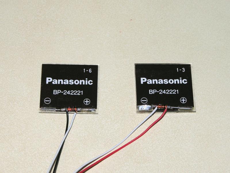
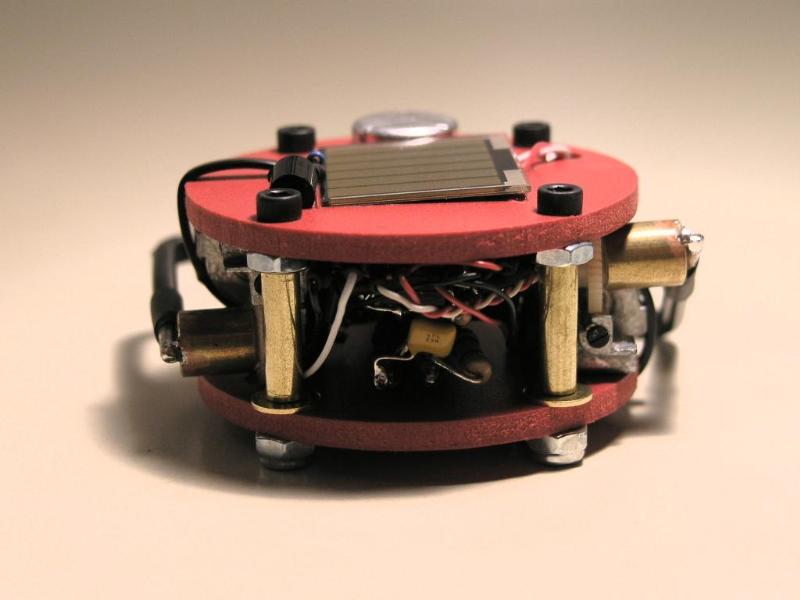
Solder a bypass diode and power wires to the two solar cells. Use black for Gnd, white for the series connection, and red for Vcc.
Use a Dremel to scuff out the Sintra so that the diodes can fit. Take care not to scuff the Sintra outside where the solar cells go. Once done, epoxy the cells into place.
Follow the Junkbots book instructions to free-form a Miller solar engine. Test it by wiring (not soldering) the engine, solar cells, and motors.
Free-form the latch circuit. Test it by wiring (not soldering) on the motors and photodiodes. Test power the circuit with a 3V battery pack.
Assemble the robot. Salvage two four-port cables from a CD-ROM. Use this for the motors and top solar cell and photodiode. Feed the solar cell wires thru the holes for the motors. Feed the PD wires thru the wire-tie holes. For the flagella caps, use wire caps (one black, one red).
Lessons Learned:
1) Not-so super glue. We first attached the flagella hooks to the motor by means of super glue. This broke and we learned that super glue does not bind well to nylon (such as the gears). Use epoxy instead.