Scuff Circuit

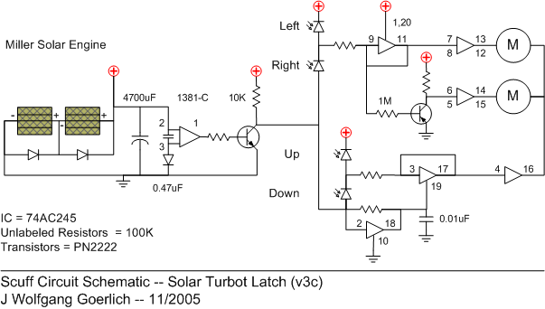
Scuff uses a circuit I call a Solar Turbot Latch. The concept is to select a motion and latch that motion for the solar engine firing duration. Given the motor startup consumes the most current, latching instead of stopping and restarting the motor is more efficient.
When charging, the 10K pull-up resistor disables the 74AC245 chip (pin 19). It also holds the photo voltage divider high, keeping the buffers from oscillating.
The solar engine enables both voltage dividers when it fires. The signal passes over the 100K resistors to the buffers. The 100K resistor at 0.01uF capacitor on pin 19 forms an Nu- neuron. It provides a millisecond delay, giving the voltage divider and buffer just enough time to decide the direction.
After a millisecond, the 74AC245 enables. The buffers’ outputs, tied to their inputs, latch the signal. A second set of buffers sits between the latch and the motor, keeping the motors from interfering with the latch.
The Left/Right buffers and transistor inverter ensure that the two motors run in different directions (either Vcc/Gnd or Gnd/Vcc). The Up/Down buffer flips the shared motor input between Vcc or Gnd. One motor will spin either forward or reverse.
When the Miller solar engine resets, the Vcc pulse turns off the voltage divider. It immediately disables the 74AC245 via buffer (2, 18). The turbot rests and charges.
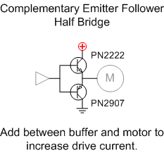
Wilf Rigter refined this circuit. Scuff uses efficient worm gear motors. These draw around 35 mA. For more power hungry motors, Wilf recommended adding the following between the buffer outputs and the motors.

Wilf wrote: It is best described as a "complementary emitter follower half bridge". The first part describes the actual components used (bipolar transistors), their configuration (emitter output), and non-inverting logic (follower). The "half bridge" describes its use as bidirectional power driver.
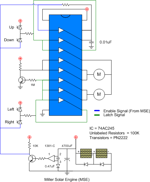
Wiring Diagram:
