
| Back to Summary |
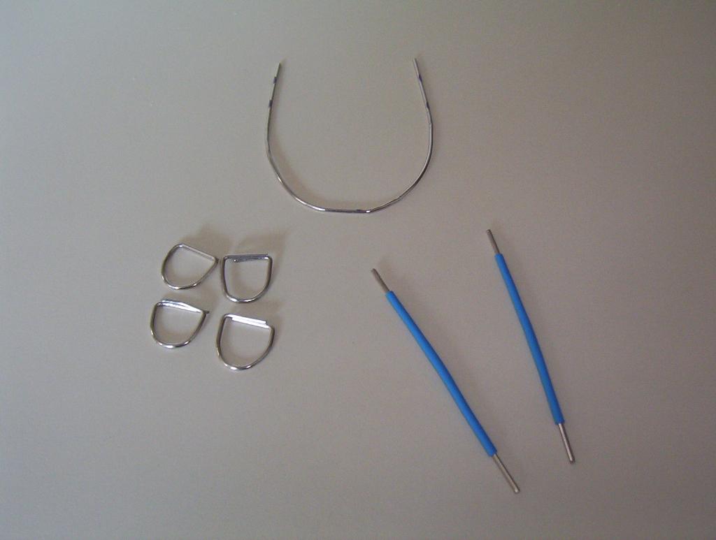
Make the motor mounts by cutting four 6cm sections of paperclips. 6cm provides enough paperclip to wrap around the motor with 1cm remaining on each side. Bend this 1cm over on a 90 degree angle, forming a U-shape with a flat cover.
Make the solar cell braces by cutting two 7cm sections of paperclips. Straighten these sections, then cover with 5cm of heat shrink. This will leave 1cm on each side bare.
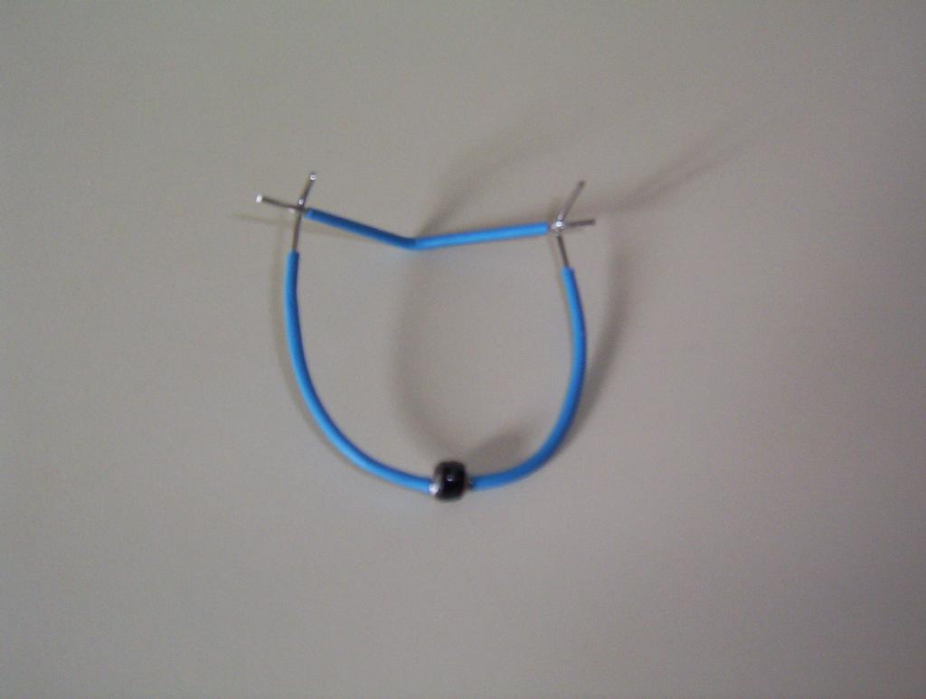
Start the frame by cutting one 14cm section of paperclip. First flatten this paperclip, then bend in a gentle arc.
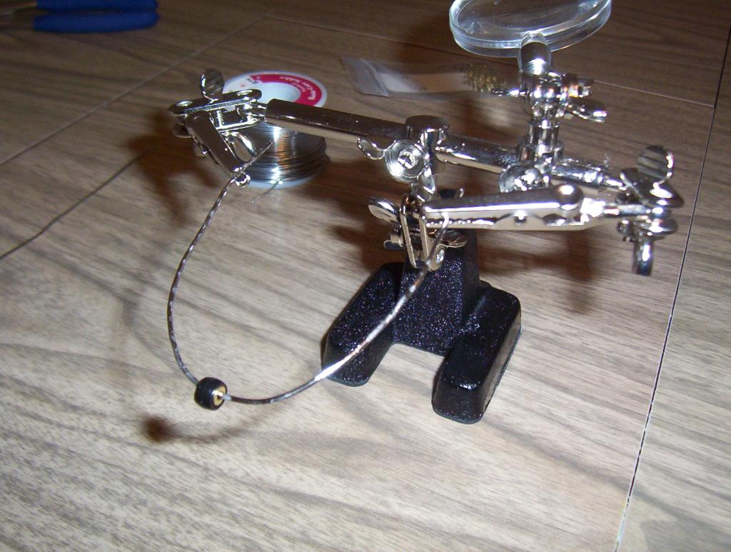
Solder the brass washer, then the bead, then the final brass washer to the middle of the frame. This makes the rear wheel.
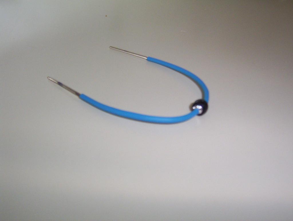
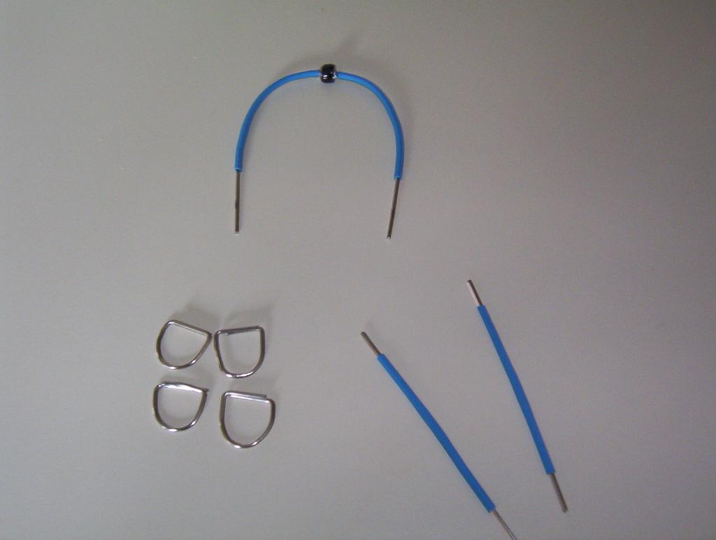
Finish the frame by applying heat shrink tubing to both sides of the rear wheel. Cut the heat shrink to leave 2cm bare at the ends of the frame.
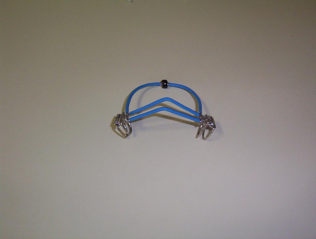
Bend the solar cell braces in the middle at approximately 120 degrees. Bend the frame down at a 90 degrees 1 cm from the end, and solder the first brace at this bend point.
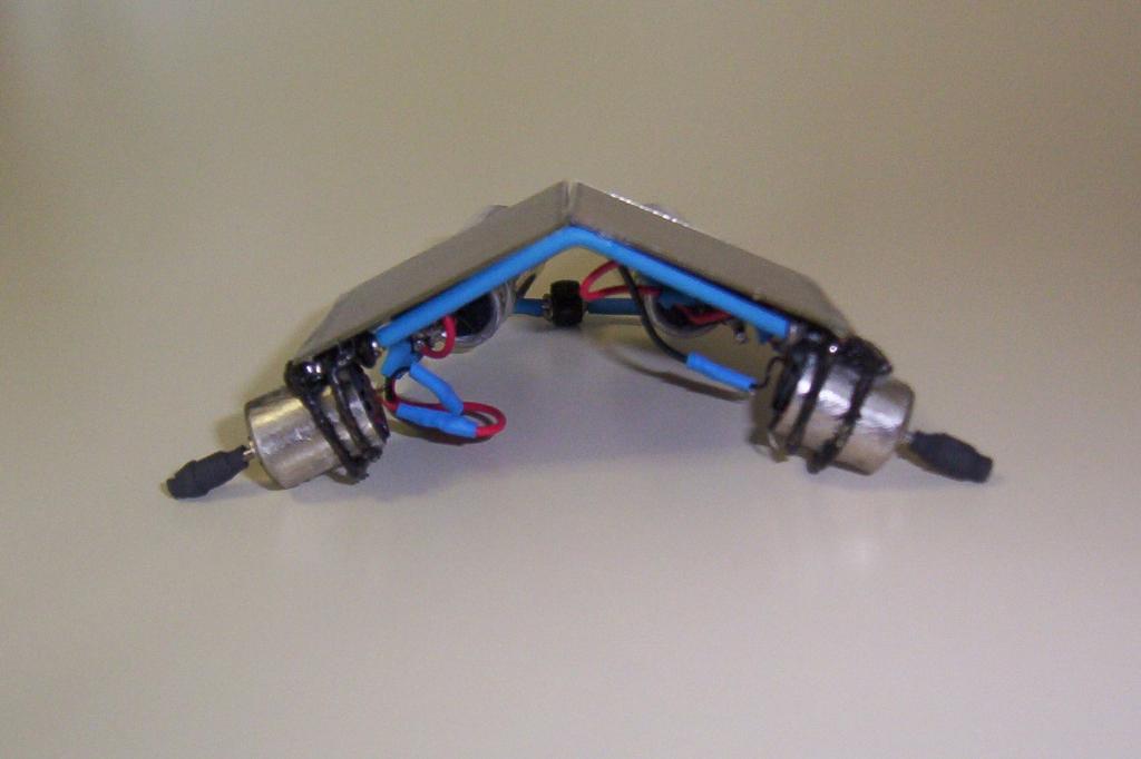
Solder the second solar cell brace into place 1cm behind the first brace, at the point where the heat shrink tubing ends. After this is soldered in place, complete the 90 degree bend in the frame so that it supports both of these loops. (Note: the photo also shows unfinished motor mounts, which can be ignored.)

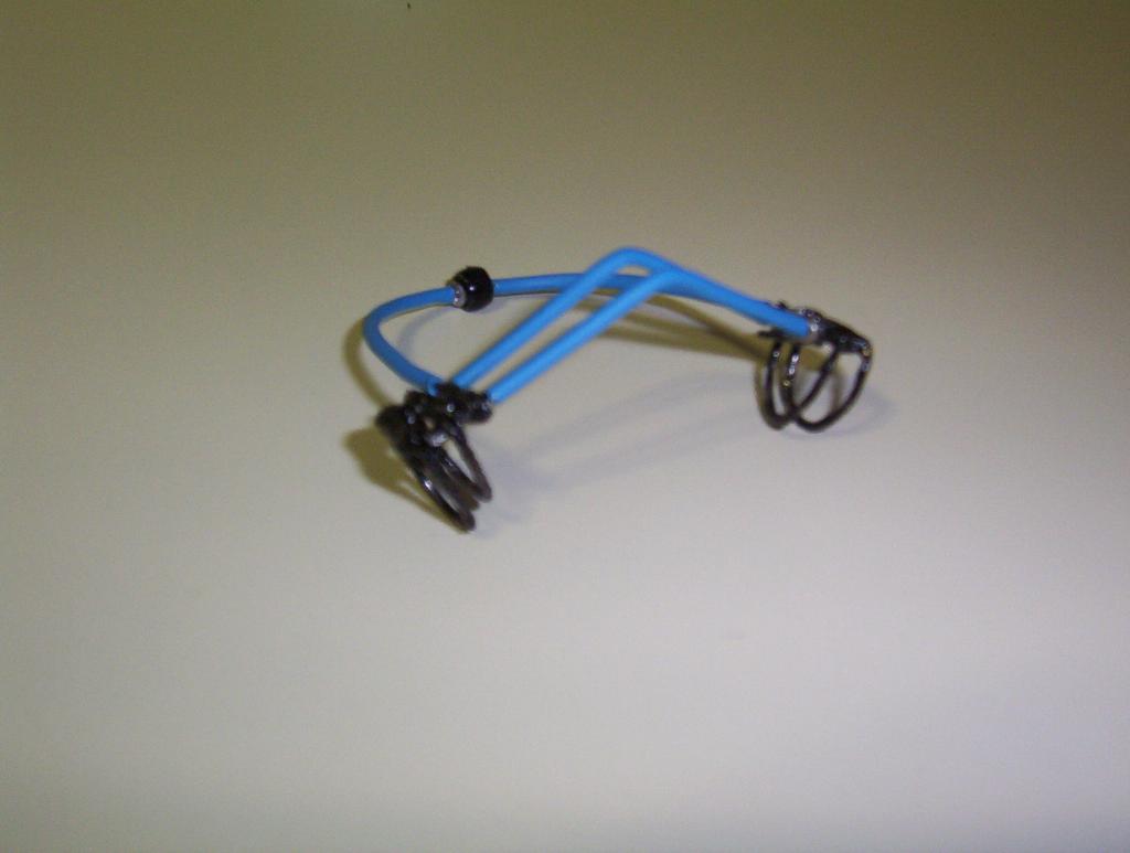
Solder two motor mounts to each side of the solar cell brace.
Paint the bare paperclips on the frame, braces, and motor mounts with Plasti-Cote. This is to ensure that the motors are held securely in place.
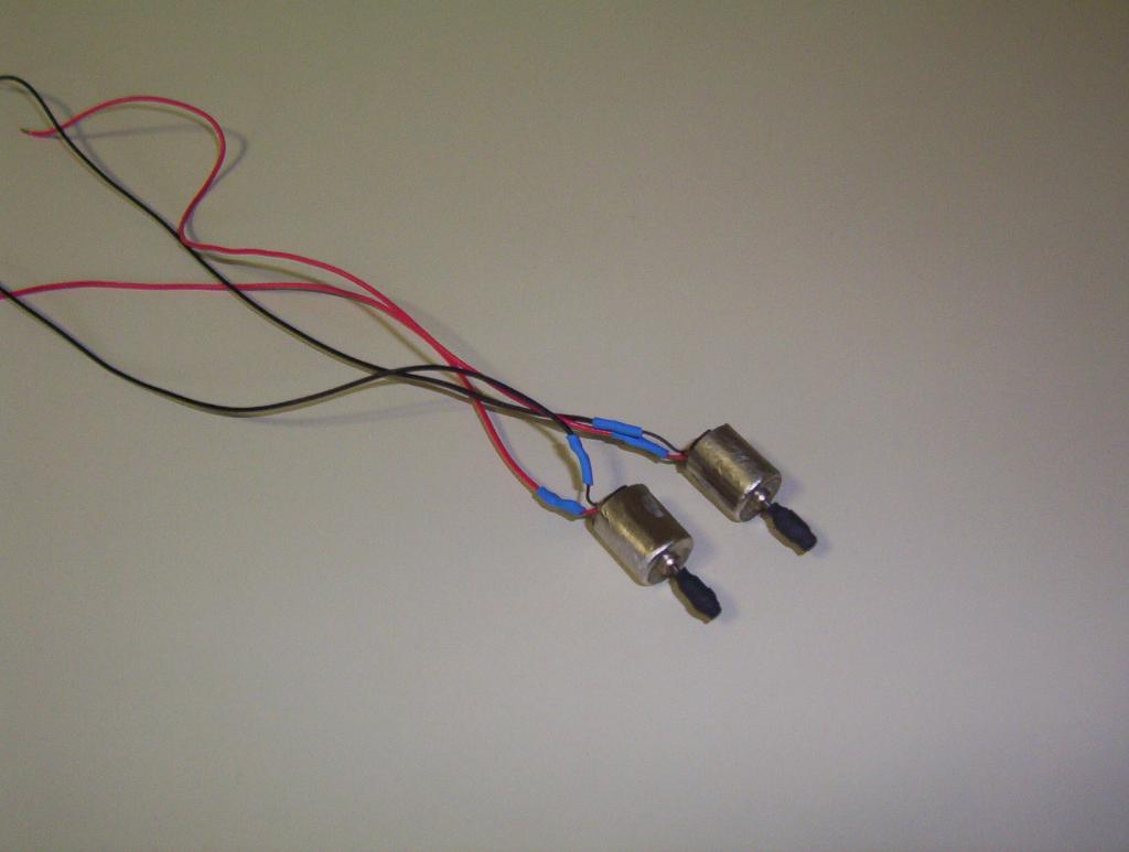
Take the two worm-gear motors. Apply heat shrink to the motor shafts, lightly sand the motor casings for best contact, and solder on wires.
Slide the motors into position. The motors will slide back into the motor mounts, but will be stopped by the bend made in the frame around the solar cell braces. Glue this part of the frame to the motors.

Glue the solar cells into position on the solar cell braces.
Free-form two Miller Solar Engines, place glue on the solar cells and the frame, and glue the Millers into place. Then solder the motors and solar cells onto the Miller Engine.

1) Attaching the motors. We had a lot of trouble soldering the motors into place. The motors would get too hot, and there was concern about the motor wiring melting. The solution was to paint the motor mounts in Plasti-Cote, and use the rubbery coat to hold the motors into position.
2) Glue. We originally used Super Glue (CA) to attach the motors and solar cells. This provided too inflexible, and we switched to white hobby glue.
3) Miller Engine. The BP-373334 solar cells put out a maximum of 5V. As solar engines work best if they fire 80% below the solar cell output, we used a 1381Q (3.8V) trigger. Unfortunately, we did not realize at the time that the diode adds another 0.7V to the trigger voltage, which means the Miller Engine triggers at ~4.5V. The end result is that the Twin Mills only moves in extremely bright light.
4) Motors. Kyle Simmons pointed out that the worm-gear motors would be better used as gear motors; on a Turbot, for instance. If we were to build this type of robot again, we would use more common motors.