Parts List
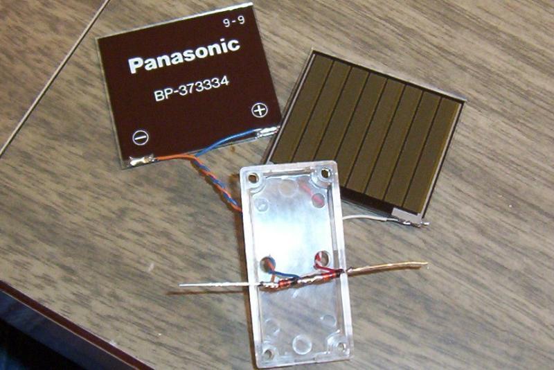
2 - Panasonic BP-3733 Solar cells1 - Mycroft2152's Holmes SE Board
1 - Clear Servo (Solarbotics GM4)
1 - High-Output IR LED (Radio Shack 276-143)
1 - 1F Aerogel Capacitor (Solarbotics CPAG1.0F)
1 - 555 IC
1 - 2n2222 Transistor 1 - 100K Resistor
2 - 1N914 Diodes
2 - Self-sticking cushion feed (Radio Shack 64-2346)
1 - Gumby Rubber Feet (Solarbotics GRF)
1 - Blue Wire Gumby Legs (Solarbotics Wleg)
Place heat shrink over the IR LED, leaving the space at the top of the LED open.
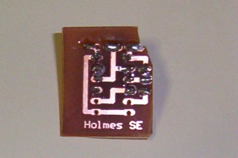
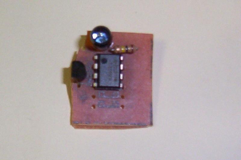
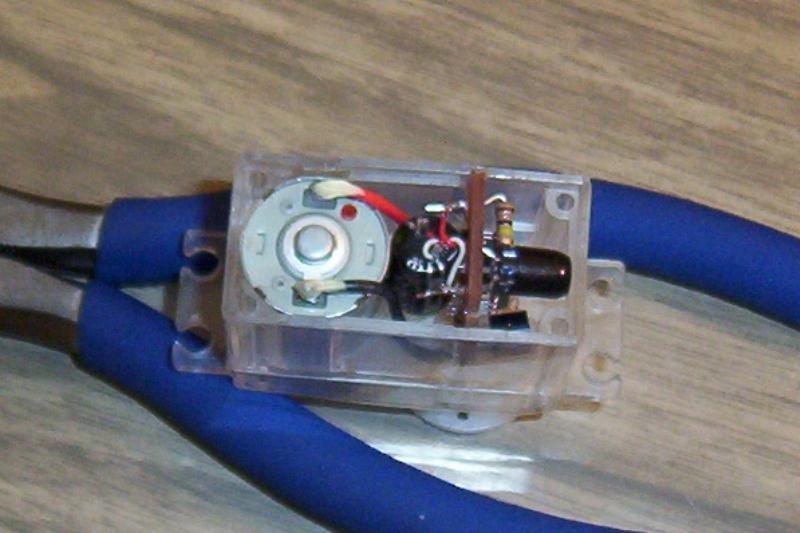
Populate the Holmes SE board. Leave 1 cm long on the Vcc leg of the resistor and the Gnd cathode on the LED.
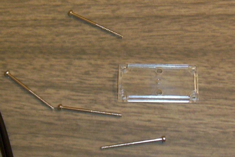
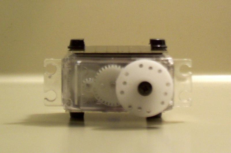
Remove the screws from the servo, taking care to keep the servo gears in place. Drill two 1/8" holes in the servo lid. We will use these holes to feed the solar cell's wires into.
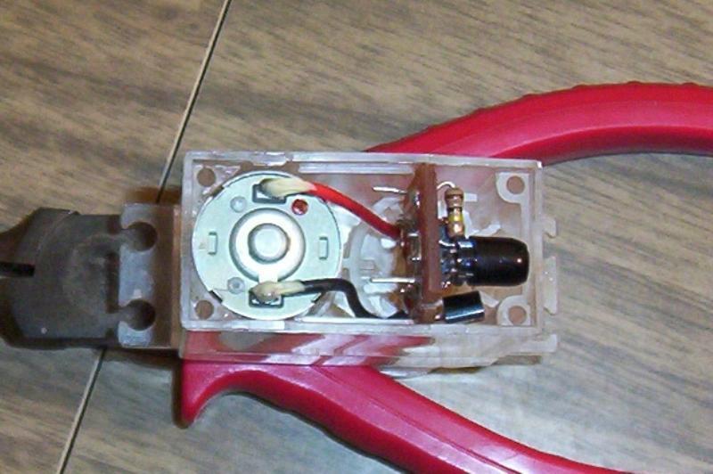
Solder the servo wire into the Holmes board. Feed the board into the servo case, pointing the IR LED away from the motor.
Put the 1F capacitor in place between the board and the motor. Solder it to the Holmes board.
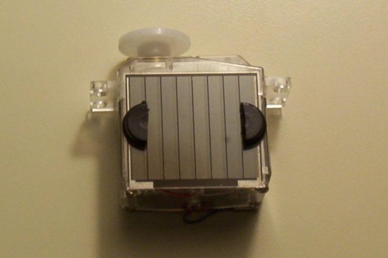
Solder wires to the solar cells. Color code is: blue + on top cell, yellow - on top; red + on bottom cell, white - on bottom.
Solder the wires to the diodes and test the voltage covering one cell and then the other.
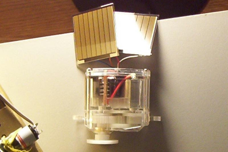
Solder a wire from the diodes to the Vcc and Gnd on the Holmes SE board. Place the cap back on the servo and screw it down. Secure the solar cell to the servo case using double-sided tape.
Take two tabs from the self-sticking cushion feet pack. Cut them in half.
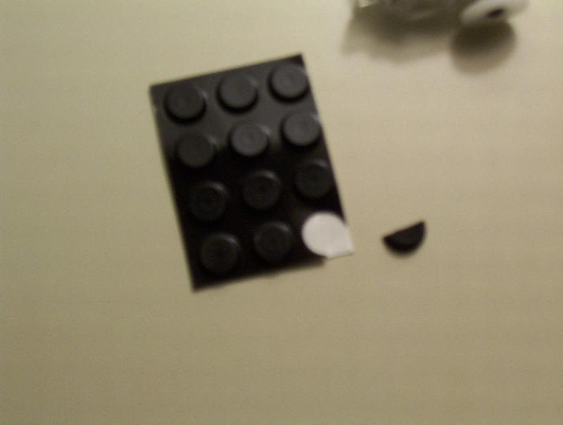
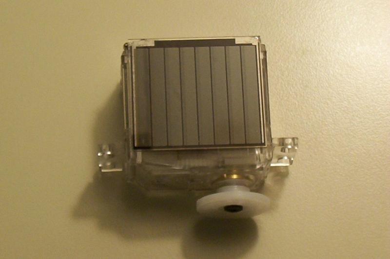
Stick the feet onto the top and bottom solar cells.
Make a 10 cm long leg from the gumby leg wire, place on the boot. Strip 2 cm of the leg to the bare copper.
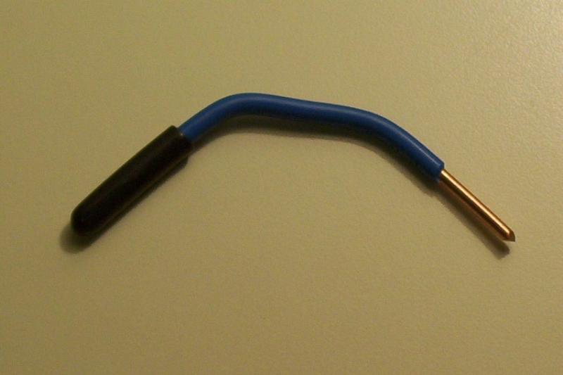
Use stiff wire to make two loops, looping around the leg and threading thru the servo's wheel. Solder the legs onto these loops.
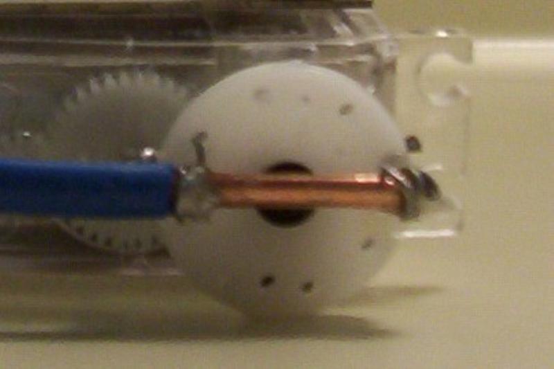
Done!

Lessons Learned:
1. Easy does it. You may have noticed the Holmes SE board has a chunk missing from the top left. I put a little too much pressure on it. Gently does it when cutting out boards.
2. Legs. I had a very difficult time soldering the legs to the wire loops. I think that pre-scoring the legs with sandpaper and using a hotter (45-Watt) iron would make it easier.