
Free Form Bicore Tutorial
What would a BEAM robotics website be without a Bicore tutorial? Yes, there are many takes on free forming the Bicore. This tutorial details the method we use. We find it handy, particularly as it leaves plenty of room for attaching wires, resistors, and other parts.
Parts List
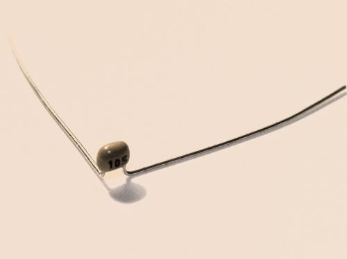
1 - 74AC240 or 74HC240 (use the 74AC240 if directly driving a motor)2 - Monolithic Capacitors (0.01µF, 0.1µF, 0.22µF, 0.47µF, or 1µF)
1 - Stripped 22-gauge wire or scrap lead
1 - Heat shrink tubing
Step 1: Before we Begin
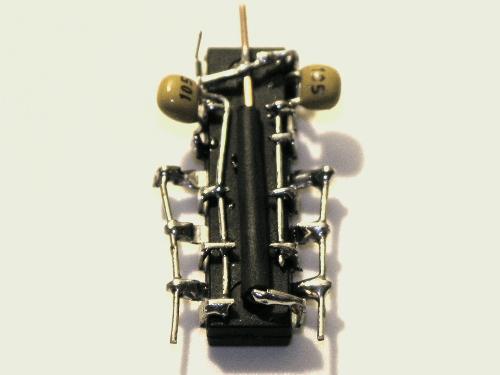
In this tutorial, we will be building traditional BEAM Bicore. A Bicore is a two neuron oscillator. The primary components are two capacitors and a chip. Let us take a moment to look at these before beginning.
We will be using monolithic capacitors, which are not polarity sensitive. However, caps that are backwards (or upside-down) are hard to read. Unless you have a excellent memory for capacitor values, we suggest soldering such that the value is facing outwards. When this tutorial mentions the left or right pin, hold the cap so you can read the value and then select the direction.
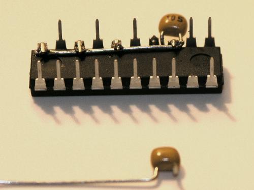
The 74xx240 chip is illustrated in Figure 1. The left blue chip is the top up view, where the IC is sitting on its pins. The right green one is bottom up view, sitting on the plastic with the pins in the air. You may want to refer back to this pin-out as you build.
Please see the datasheet for detailed information on the 74AC240.

For the Bicore, we will be using the inverter on pins (2, 18) for one Nv neuron, inverter (17, 3) for the other. The remaining inverters will be ganged up. This provides extra current for driving motors plus isolates the Bicore from motor noise.
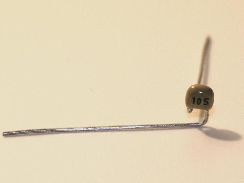
Step 2: Bend Nv(17, 3) Capacitor
Start with one of the capacitors. With the value facing you, bend the left lead straight back. This bend is flush with the cap's body.
About 3mm beneath the cap, bend the right lead to the left.
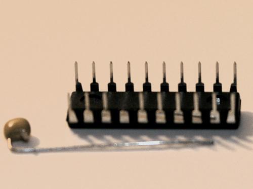
Step 3: Snip the Chip and Cap
Snip pin 17 (fourth over). Snip the capacitor's left lead to an approximate length of 2mm. Save the lead.
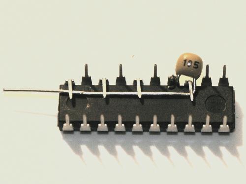
Step 4: Pin the Capacitor in place
Hold the capacitor so that you can read the value. Fit the capacitor's left lead into pin 17. Bend pins 18, 15, 13, 11 down flat. Use these pins to hold the capacitor in place.
In effect, the capacitor connects the Nv output (pin 18) to three inverters' inputs.
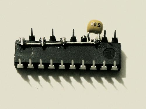
Step 5: Solder the Capacitor down
Solder the capacitor in place. Trim the pins flush.
Step 6: Bend Nv(2, 18) Capacitor
Take out the second capacitor. Bend the left lead straight back. Bend the right lead straight to the right.
Step 7: Snip the Chip and Cap
Snip pin 2 (second over). Cut the capacitor's left lead, again to a length of 2mm.
Step 8: Pin the Capacitor in place
Bend pins 3, 4, 6, 8 down. Use these to hold the capacitor in place.
The lead connects the Nv output (pin 3) to the other three inverters' inputs.

Step 9: Solder the Capacitor down
Solder the capacitor to the IC and trim the pins.

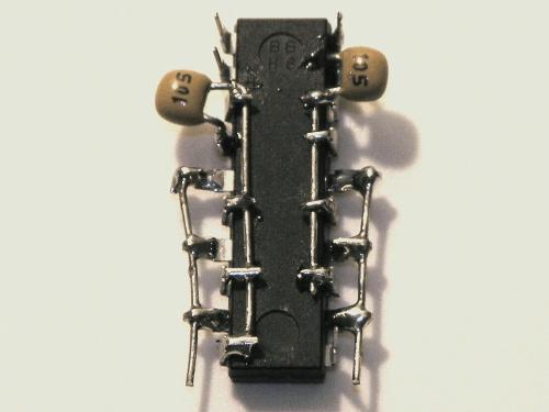
Step 10: Bend out the outputs
Bend pins 12, 14, 16 horizontally to the right. Bend pins 5, 7, 9 out horizontally to the left.
Look back up at the pin-out. These pins are the outputs.

Step 11: Hook Leads
Take the leads cut from the two capacitors. Bend them to form hooks.

Step 12: Pin the leads in place
Hook one lead on output pin 16, the other on pin 5. Bend the pins over these leads.

Step 13: Solder the output leads
Solder the output pins to the leads. Trim back the leads, leaving enough space for you to attach wires.
Step 14: Begin Connecting Ground
Strip a section of solid 22-gauge wire. Solder it to pin 10 (Gnd). Bend it so that the wire sits flat between the two input leads.
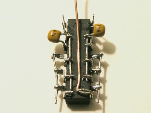
Step 15: Finish Connecting Ground
Cover the Gnd wire with black heat shrink to prevent it from touching the input rails.
Enable the inverters' output by connecting the 74AC240 enables (pin 1 and 19) to the Gnd wire. First, bend the pins in toward the wire. Then solder the connection.
Step 16: Using the Bicore
Connect V+ to pin 20, Gnd- to the Gnd wire. You can power the Bicore from 3-6V DC. This completes the free form Bicore. The final step is to decide how to use this simple Nervous Net.
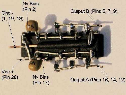
Grounded Bicore. This requires two resistors. Solder the first between Nv (2,18)'s bias point, pin 2, and Gnd. Solder the second resistor between pin 17 and Gnd. The time-out in equal 0.65(R*C) with time in seconds, resistance in M-Ohms, and capacitance in µF.
Suspended Bicore. This requires one resistor. Solder it between pin 2 and pin 17. The time-out in seconds will be roughly ( 0.65(R*C) ) / 2.
Master-Slave Bicore architecture. Free form two Bicores. Setup the first as a Suspended Bicore. Run two resistors from the first output (pins 3 and 18) to the second Bicore’s biases (pins 2, 17). The first Bicore is the Master (MB) as it sets the oscillation time. The second is the Slave Bicore (SB), for it follows the MB’s time. If the two slave resistors equal the MB’s resistor, then the delay is 180-degrees. The SB does the opposite of the MB. If the slave resistors are wires, the SB does exactly what the MB does (0-degrees delay).
Phototropic Suspended Bicore. This requires two photodiodes. Solder (or wire) the first photodiode's cathode to the second's cathode. Connect the first photodiode's anode to pin 2, the second anode to pin 17. The time-out will be dependent upon the light level. See the BEAM FAQ for more information.
Motor driving. The 74AC240 has eight inverters, two of which we use for the Bicore, six of which we use for output.
Have fun!
J Wolfgang Goerlich
December 2005
Related Links:
For other ways to make and use free form Bicore circuits, see the following:
1. Junkbots, Bugbots, and Bots on Wheels by Dave Hrynkiw and Mark Tilden
2. Absolute Beginner's Guide to Building Robots by Gareth Branwyn
3. Andy Pang, "DIY: Bicore Head"
http://www.solarbug.com/tutorial5.html
4. Ian Bernstein, "How to free form the Bicore"
http://www.beam-online.com/Robots/Tutorials/Freeform/Bicore/bicore.html
5. Jérôme Demers, "How to free-form the Bicore"
http://robomaniac.solarbotics.net/freeform/Bicore.html