
BEAM Biomorphic Lexicon -- Notes and References
The BEAM Biomorphic Lexicon is a collection of symbols and methods used for designing Nervous Nets. The lexicon can be confusing as the notes we have span a decade or more in this technology. Needless to say, it has evolved over this time. This page contains some remarks on and references to commonly used symbols.
Next to the symbol, you will find the corresponding circuit. Some symbols represent multiple circuits. Which circuit is used often times depends upon the builder or the parts at hand. Also, please note that the Schmitt inverter is used for convenience. BEAM neurons can also be built from standard CMOS inverters.
I am compiling a definitive list for drawing Biomorphic maps. If anything is missing or unclear, please drop me an email.
J Wolfgang Goerlich
July 2005
Biomorphic Symbols
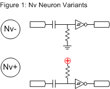
The Nv or Nervous Neuron is the most common component in a BEAM Nv Net. The symbol is simply a circled Nv. When referenced to Gnd, it is called an Nv- or plain Nv. It is an Nv+ when referenced to Vcc. [ 4, 9 ]
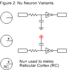
The next component is the Nu or Neural Neuron. The Nu can be used as an integrate-and-fire neuron; hence the symbol is a line into circle. An Nu or Nu- is tied to Gnd. An Nu+ is tied to Vcc. [ 4, 5, 6, 7 ] When used in a Pulse Neutralization Circuit (PNC), the Nu+ may be marked RC for Reticular Cortex. [ 4 ]
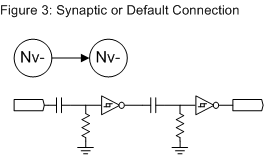
Sequentially is the most common method of connecting neurons, where one output runs into the next input. This is sometimes referred to as the Synaptic Connection.
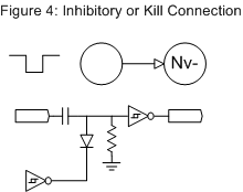
One can inhibit or kill an Nv- Neuron by sending a Gnd pulse to its bias point. If the Nv- was active when the signal comes in, the pulse immediately deactivates the neuron. The Nv- cannot become active so long as Gnd is applied. This is referred to as the Inhibitory Connection or Kill Connection. [ 1, 9 ]
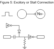
An Nv- can be activated and held active using an Excitory or Stall Connection. This connection sends a Vcc signal to the bias point. If the Nv- was not active, it will become active immediately. The Nv- will remain active so long as the signal is applied. [ 9 ]
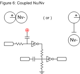
One neuron can be coupled to another using a resistor. This connection changes the timing of the second neuron. In Living Machines, this is represented as two joined circles. Tilden later changed to using a plate or line. [ 4, 9 ]
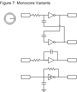
The Monocore architecture can be represented as an Nu within a circle. Monocores operate as tri-state cores, High/Low/Oscillate (HLO). A Monocore circuit can take many forms, including modified Slave Bicores, Buffered Monocores, and Schmitt Oscillators.
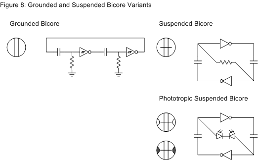
There are several symbols for representing the Bicore architecture. A Grounded Bicore shows two halves. Note that this is also the symbol used for Slave Bicores (the idea being that the Slave is effectively grounded by the Master Bicore). The Suspended Bicore has a single line intersecting the halves, representing the single resistor. [ 5, 6, 8, 10 ]
Phototropic Suspended Bicores have to semi-circles used to represent the light sensors. These are colored in when the Phototropic Bicore is wired to turn towards the dark. [ 6, 8 ]
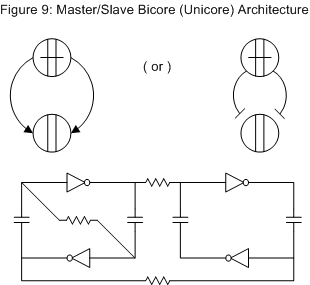
The Master/Slave Bicore architecture is comprised of two coupled Suspended Bicores. This is also known as the Unicore (for Unified Bicores) architecture. This may be represented by the default connection or, more accurately, by the coupling plate. [ 5, 6 ]
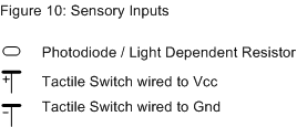
Data in. Light sensors are represented as small ovals. Tactile switches are represented as a thick line with a symbol showing the resulting output (e.g. + for Vcc and – for Gnd). [ 3, 4, 5 ]
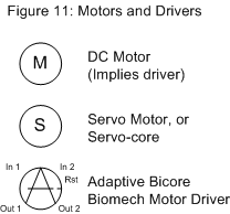
Data out. The motor symbol is a circled M. This implies a motor driver. The servo motor symbol is a circled S. This symbol may also be used for the servo motor plus the driving core, such as an Servocore. The Adaptive Bicore Biomech motor driver (Abcore) is a symbol resembling a Suspended Bicore crossed with the letter A. [ 10, 11 ]
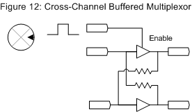
The Cross-Channel Buffered Multiplexor uses a buffer such as the 74AC245. Driving the Enable pin high disables the buffers. The signal then follows the resistors. [ 4, 7 ]
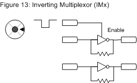
The Inverting Multiplexor (IMx) uses a CMOS inverter chip, such as the 74AC240. The signal follows the resistors when the Enable is high. Driving the Enable pin low turns on the inverters. The signal output signal is inverted. [ 10 ]
Other symbols that can be used in Biomorphic maps include the Solar Engine (circled SE) and the SIP-Socketed resistors. [ 5, 10 ]

References
1. Mark W. Tilden U.S. Patent #5,325,031 "Adaptive Robotic Nervous Systems and Control Circuits Therefor", Filed 15 June 1992, granted 28 June 1994
2. Mark W. Tilden, VBug 1.5 "Walkman" Notes, 1994
3. Mark W. Tilden, VBug 1.6 "Walkman Solar" Notes, 1994
4. Brosl Hasslacher and Mark W. Tilden, "Living Machines", 1995
5. Mark W. Tilden, "BEAMant 6.0 Series Mobile Robot: Configuration Details", Telluride Neuromorphic Engineering Workshop, 1997
6. Mark W. Tilden, BEAMant 6.0 Notes, 1997
7. Brian O. Bush, "BEAM Robotics Tek - Nervous Networks", 1998
8. Brian O. Bush and John A. de Vries II, "BEAM Robotics Tek - Advanced Nervous Networks", 1998
9. Mark W. Tilden and Richard Piotter, "[alt-beam] Nu interconnections (from MWT himself!!!)", 31 Mar 1999
10. Solarbotics Bicore Experimenters PCB Documentation: BC2 Bicore, BC3 Bicore, Inverting Multiplexor (IMx), MD2 Motor Driver, MSE1 Miller Solar Engine, and SC1 ServoCore Driver, 2001
11. Dave Hrynkiw and Mark W. Tilden, "Junkbots, Bugbots, and Bots on Wheels"