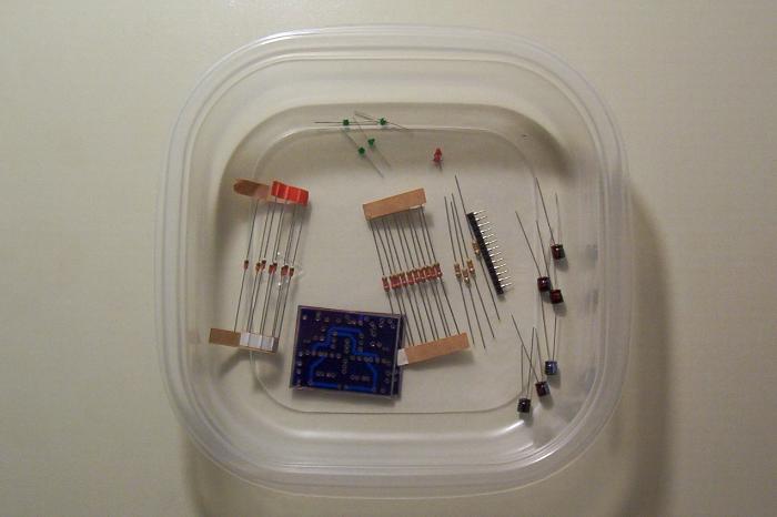
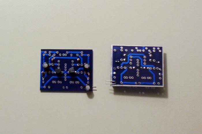
Gather the parts.
Start by soldering down the three 47 uF capacitors. Leave the leads long on the power filtration capacitor. You will use these leads to run power to the Abcore board later.
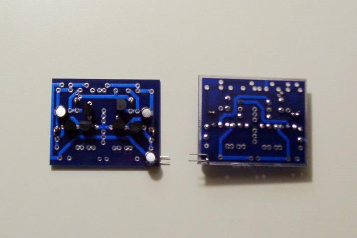
Add the four diodes. The spacing is such that you must bend the diodes. Solder the diode cathode down flush, then bend the anode back toward the board, and solder in place. In the photograph, the diodes’ cathodes are pointing toward the top of the Abcore board.
Solder the two 2N3906 transistors. Going left to right, the first transistor faces the top of the board and the second faces the bottom.
Next, solder the four 2N3904 transistors in place. The top two 2N3904s face left. The bottom two 2N3904s face the bottom of the board and the top of the board, respectively.
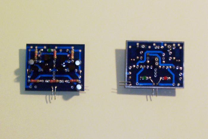
Solder the indicator LEDs in place. The ground trace runs around the perimeter of the Abcore boards, so the LEDs' cathode goes into the hole closest to the outside of the board.
After the LEDs, solder down the 4.7K input resistors. Note that you may want to use SIP sockets for these resistors, depending upon what you want the Abcore to do. These resistors set the load level necessary for the Abcore to toggle.
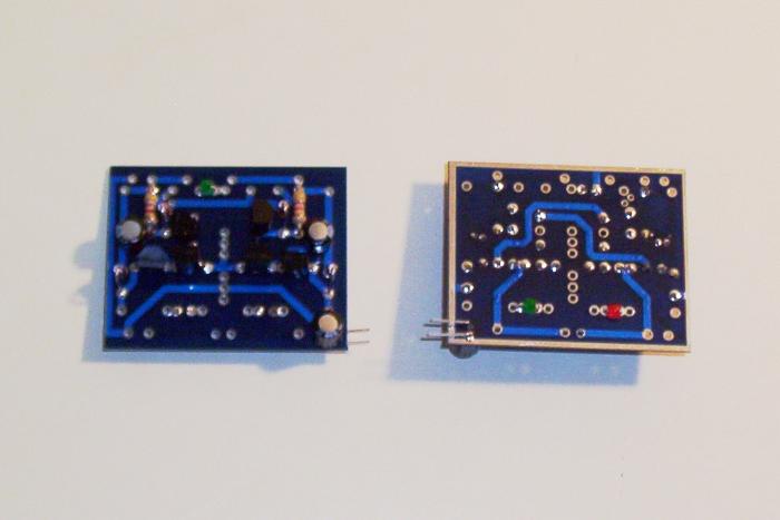
Next, solder down the four 2.2K resistors.
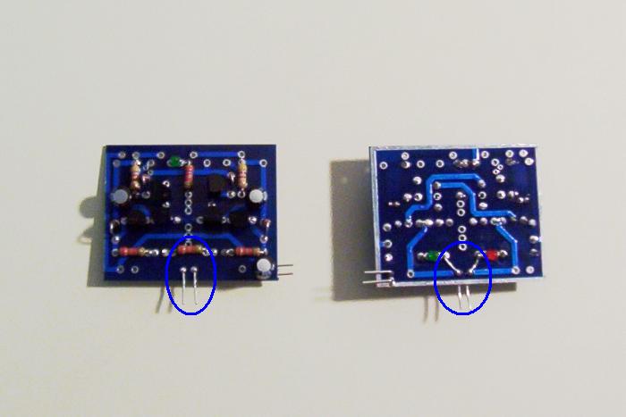
Important: the Abcore board does not have the outputs connected by default. Leave the leads long on the 2.2K resistor across the outputs (located between the output indicator LEDs). Bend the leads forward to the output pins, solder in place, and leave the remainder in place for soldering the motor to.
If you are going to experiment using biased resistors, solder in SIP sockets. The Vcc trace runs down the middle of the board. Solder two SIP sockets on this trace. The bias points are next to the 4.7K resistors, above the diodes. Solder one SIP socket into each of the two bias points.
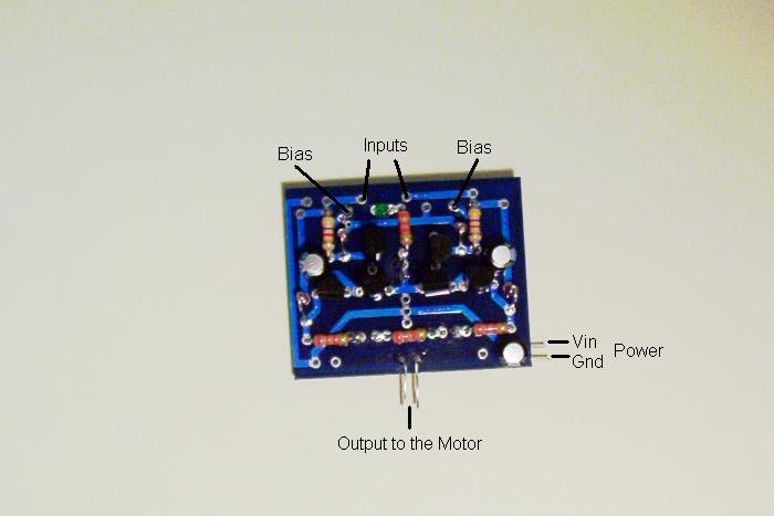
To finish, connect the power and motor to the leads. To control the motor, run inputs to either the bias or input points.
Click on the photograph to see these points labeled.