| Back to Summary |

Junkbots Mini-sumo Build Sheet

Parts List

1 - Sintra, 6 cm by 11 cm, black
1 - Sintra, 3 cm by 6 cm, red
2 - Roller lever SPDT switches (Radio Shack 275-017A)
1 - Velcro, 1 cm wide
2 - Socket Head Screws, 4-40 x 1-1/2" (Great Planes GPMQ 3020)
4 - Flat Washers, #4 (Great Planes GPMQ 3402)
2 - Hex Nuts, 4-40 (Great Planes GPMQ 3304)
2 - Solarbotics GM2 with GMPW wheel


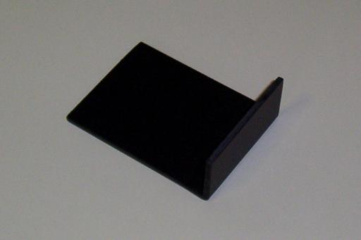
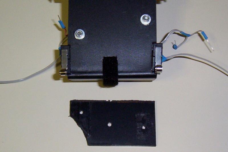
Cut a section of Sintra measuring 6 cm by 11 cm. Bend the Sintra at a 90-degree angle to form a "battering ram" measuring 3 cm from top to bottom. Sand the edges smooth.

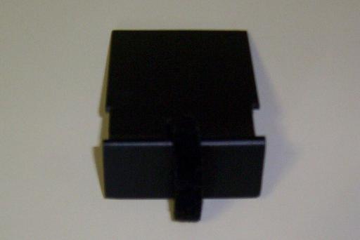
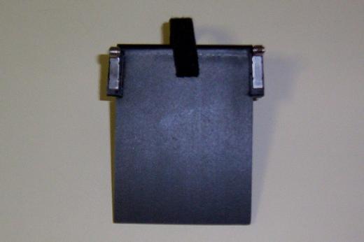
Cut a gash near the middle of the width and about 1 cm from the battering ram. This gash must be big enough to fit the velcro thru. Then cut two mounts for the roller switches. These cuts are 3 mm deep by 2 cm wide, and are right behind the battering ram.

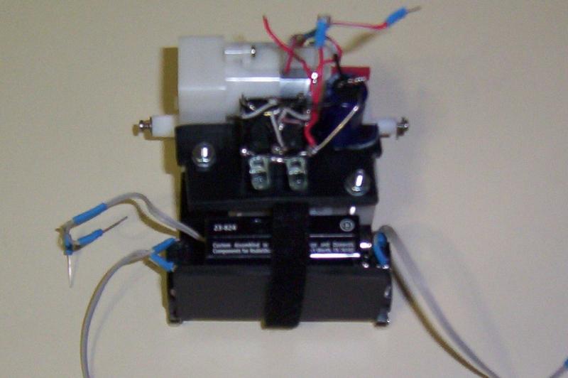
Attach the roller SPDT switches so that the wheel is toward the front battering ram.

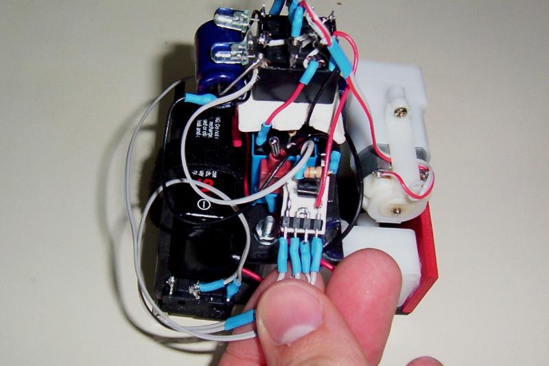
Cut a piece of wire from a floppy drive cable. Solder the wire onto the motor, and then make pins for the motor attachments using legs from capacitors.

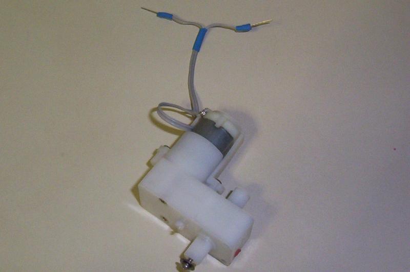
Cut two more pieces of wire and solder them onto the switches. These are positioned to be live, high, on, when the switch is depressed. Make pins as we did for the motor attachments.

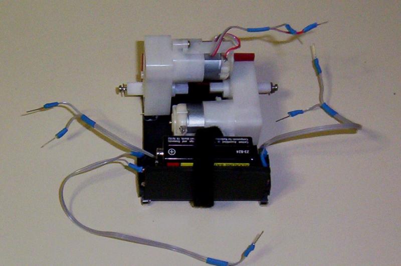
Glue down the GM2 motors. We used the same alignment as used in Junkbots Book, Figure 12-44 on page 272. Use the red Sintra to brace the rear of the motors.

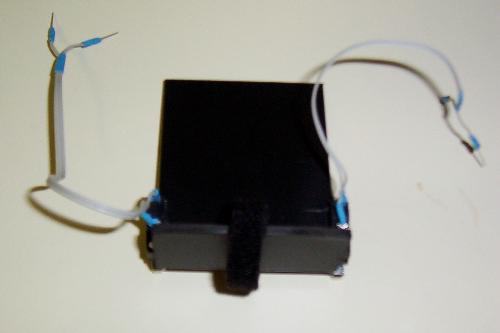
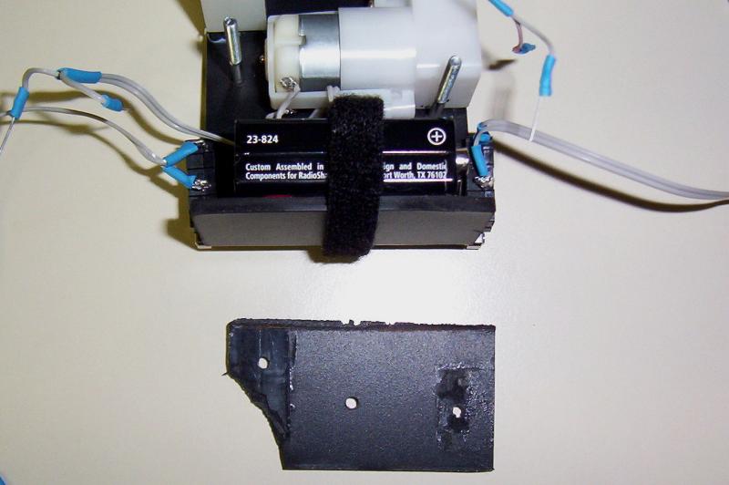
Velcro down battery to the battering ram. Battery ram, get it! Ha, ha. Oh, never mind -- Joe did not find this funny either.


Cut a piece of scrap and tape it onto the bottom of the case. Drill two 7/64" holes: centered between the battery and motor on the left, between the motor and the battery on the right. Untape the Sintra and put it aside. We will use this as the template for the relay circuit and future circuits.

Put a flat washer on two of the socket head screws, then feed the screws thru the holes. Glue them down.


Build the control circuit. Click on the link below to see images for the various circuits that we have tried.

- Junkbots Circuit w/ Tom Gray's timer

Turn on the robot and test it out. Both motors will go forward until either edge switch is opened. Then it will reverse and turn.


Lessons Learned:

1) Weight distribution. This is the second version of our Junkbots Mini-sumo. In the first version, we placed the battery near the rear as shown in the Junkbots, Bugbots, and Bots on Wheels book. We found two problems with this: 1) the front popped up really easily; 2) there was not enough weight to depress the switches. In this version, we moved the battery to the front.

2) Room to grow. The first time we put this robot together we did not include a timer. When we had to redo it for the switch problem, we decided to include the timer so as to make this qualify for competitions. The relay that we used in the timer circuit was too large, necessitating us again redoing part of the body. Furthermore, it made the circuit unstable and thus this robot is still unsuited for competitions. In future designs, all components to be added must be purchased and inspected before building the body.

3) Scooped. It was not until we had another opponent to test against, that we realized a flaw in this design. The battery ram has enough space between it and the mini-sumo arena to allow the opponent to get the scoop underneath. Our Sumovores regularly get their scoop underneath, lifting this Junkbot up. Then the edge detection trips, causing a "suicidal" reverse. One possible solution would be tactile sensors that detect an opponent and disable the edge detection.