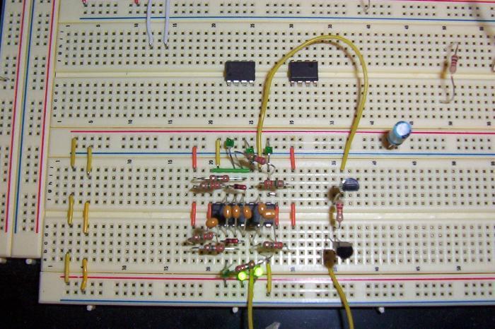
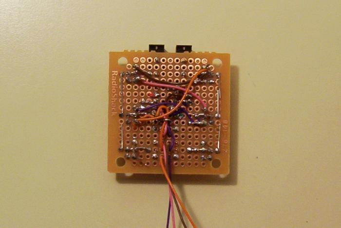
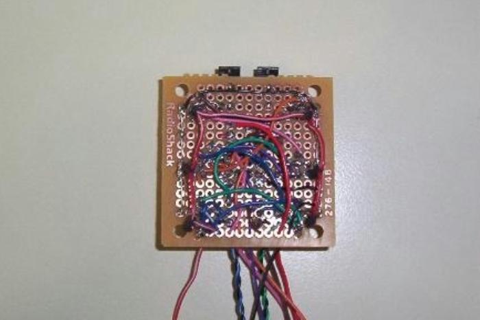
Breadboard the Nervous Net.

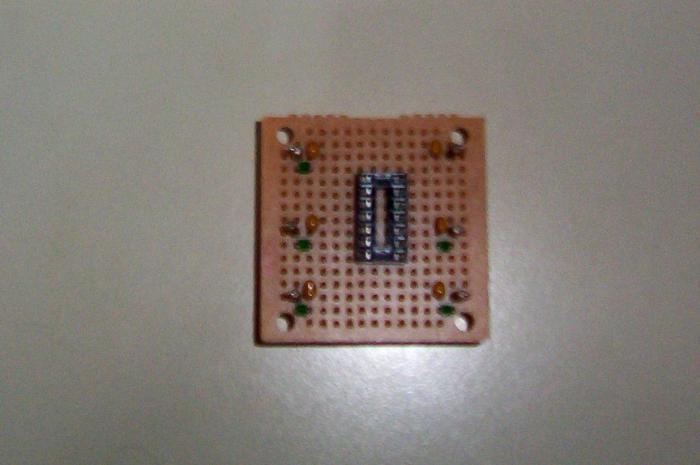
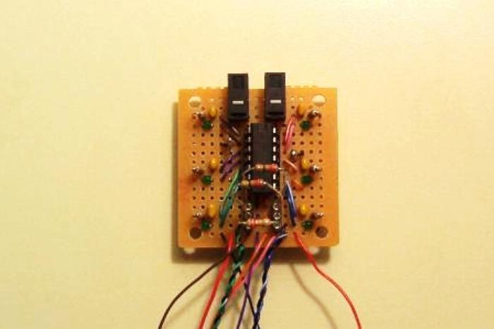
Solder down the 14-pin DIP socket. Solder down the 0.22 uF capacitor, LED, and 3.3 M resistor for Nv(1, 2), Nv(3, 4), Nv(13, 12), Nv(11, 10), and Nv(9, 8) . The last neuron, Nv(5, 6), gets a 0.1 uF capacitor, indicator LED, and 3.3 M resistor.
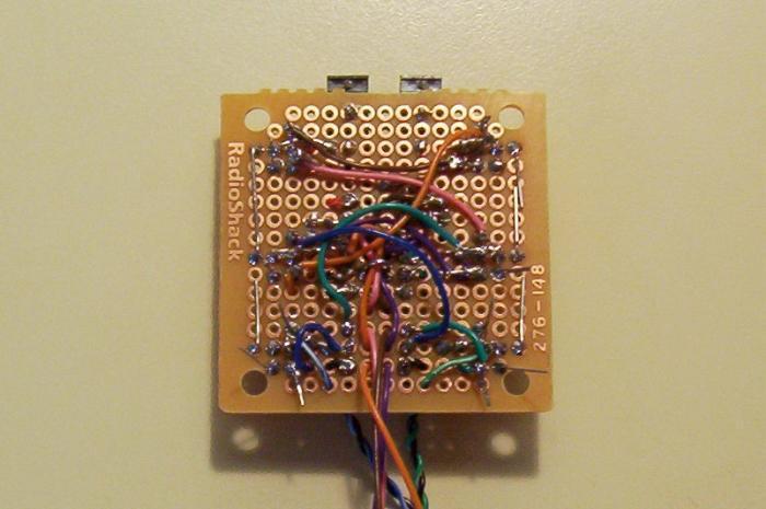
Solder down one diode on pin 3 and pin 2, and the other diode on pin 11 and pin 12. Thread the input wires, the stripped ones, to each Nv. These diodes are used for the PNC, triggered by the Bicore and the switches.


Thread the output wires, which are solid color, to each Nv on the Quadcore. The output goes from the Schmitt Inverter to the LED, from the LED to the next Nv’s input on the capacitor.
Take two mice switches. Clip the NC input. Solder the switches in place above the DIP socket. These will be used to manually trigger the PNC.
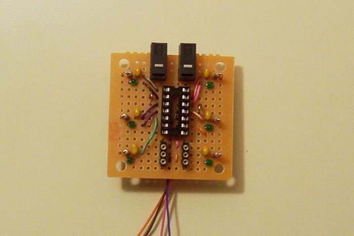
Solder down two rows of 3 SIP sockets below the DIP socket.
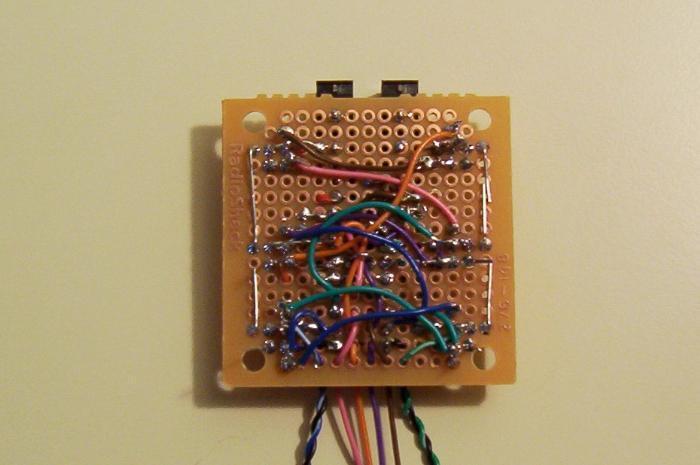
Extend the inputs from the Bicore’s Nvs. The length is approximately 10 cm. Along side the input wire, run a black wire back to the bottom SIP socket. Twist the wire. We will use this wire to attach the photodiodes, with the PDs anode going to the colored Nv input, and the PDs cathode going to the SIP socket. The resistor between the PDs then goes into the bottom SIP socket.
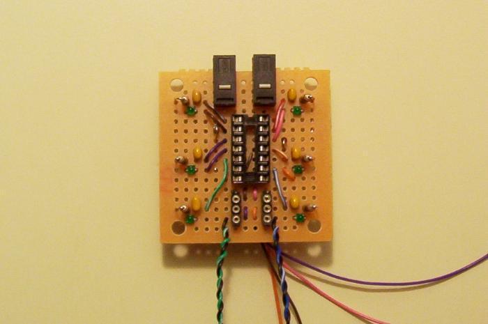
Thread and run the output wires to each Nv on the Bicore. The output goes from the Schmitt Inverter to the LED, from the LED to the SIP socket on the nearest row, from the corresponding SIP socket on the next row to the PNC diode’s anode.
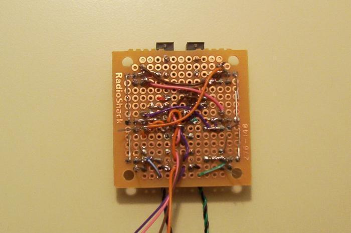
Now solder the output wires from the Bicore’s Nv to the opposite Nv, and vice versus.
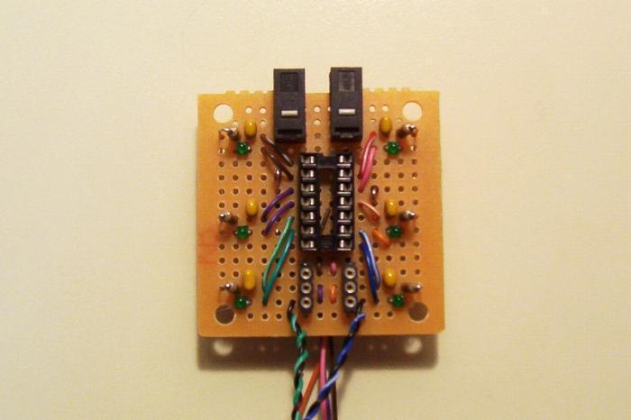
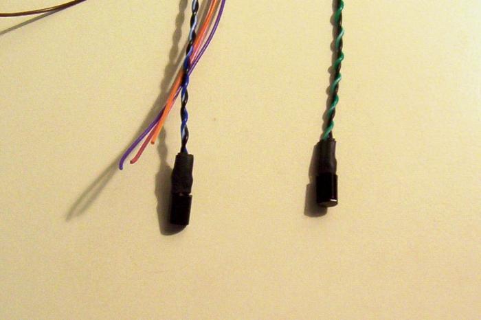
Solder the photodiodes to the Bicore Nv’s inputs. The PD’s anode goes to the colored wire, and its cathode goes to the black ground wire. Cover the anode with heat shrink tube, and the cathode with heat shrink. Then create a sleeve over the anode and cathode with one more layer of heat shrink. We will use this sleeve when securing the PDs to the frame with wire ties.
Run the ground line to the 74HC14 and to the PNC switches.


Run the power line (red solid) to the 74HC14. Run the indicator LED power line (red stripped, on resistor) to the LEDs.
Insert the resistors into the SIP sockets.
Connect the Bicore and the switches to the PNC.

Finally, temporarily solder resistor leads to the power lines, ground line, and Nv output lines. We will use these leads to connect the Nervous Net to the breadboard.
