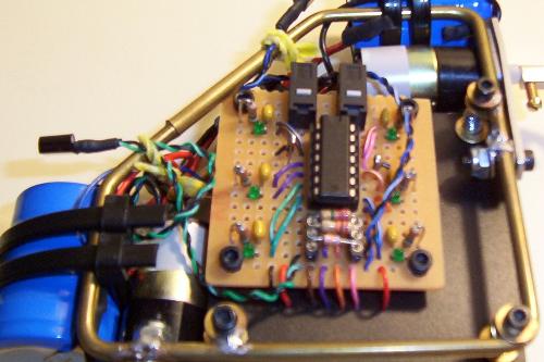
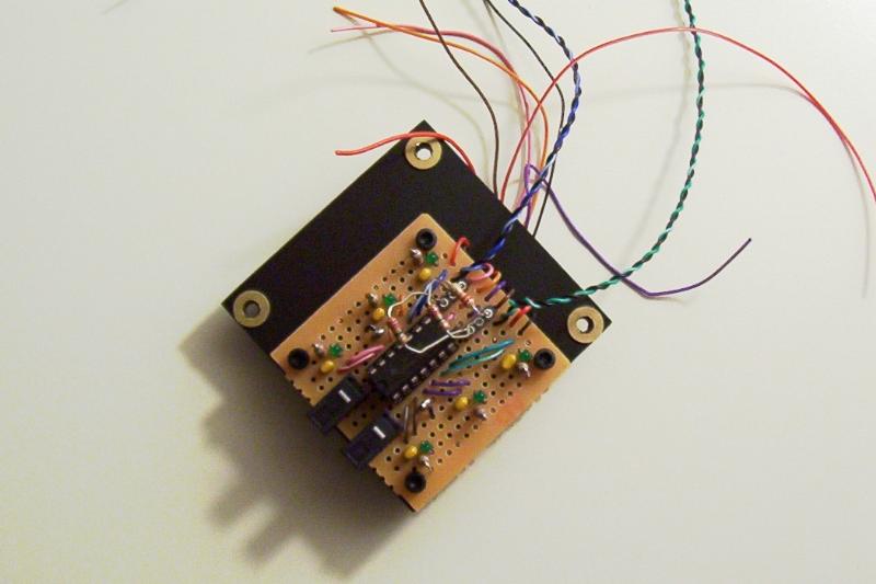
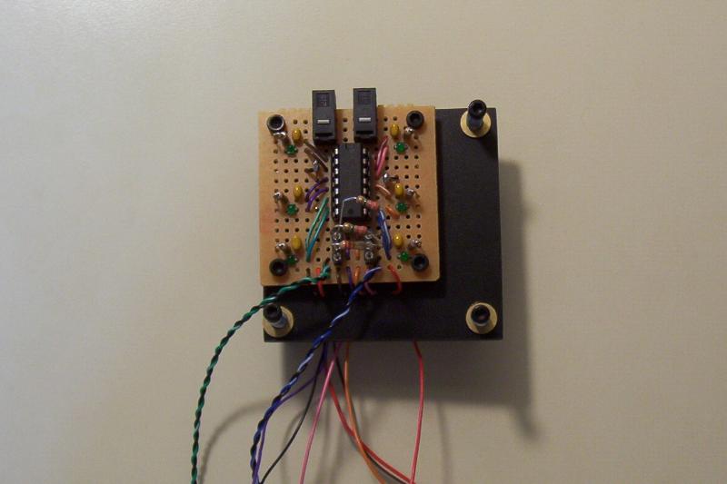
Build and test the Nervous Net board.
Click here for details.
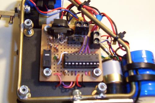
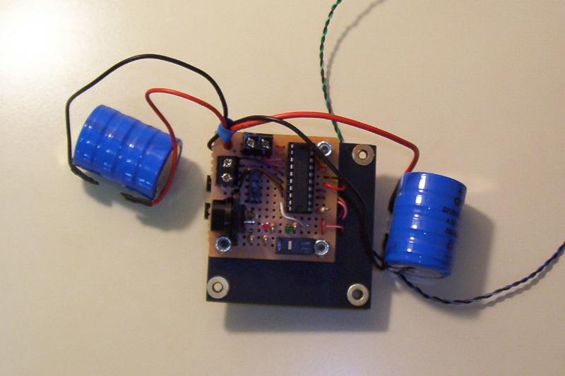
Build and test the motor and power board.
Click here for details.
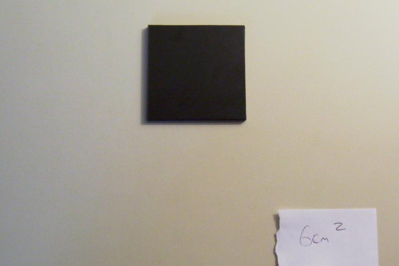
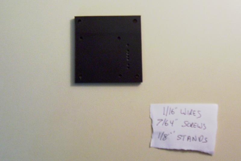
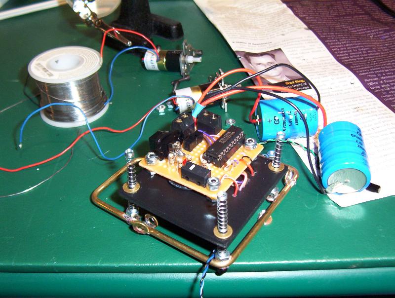
Make the board plate for the Nv Net and Motor boards. Cut out a 6 cm square from black 3mm Sintra. Sand the edges smooth. Drill six 1/16” holes for the wire feeds. Drill three 7/64” holes for screwing the boards in place. Finally, drill four 1/8” holes around the edges of the board. We will use these last four holes to mount the plate onto the brass frame.
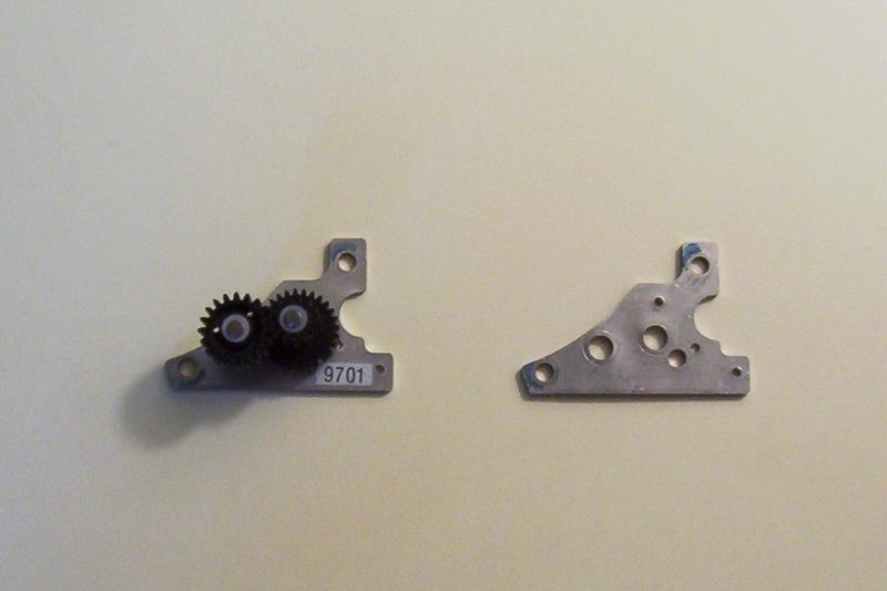
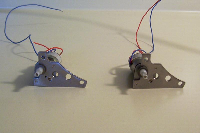
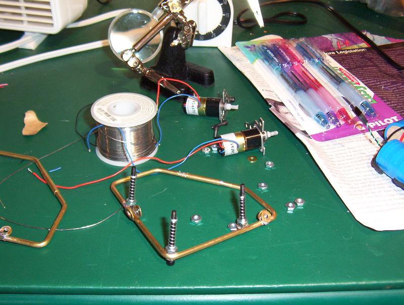
Remove the gear faceplate from the Nihon motors. Remove the gears and polish the faceplate with 160 Grit sand paper. Replace the faceplate on the motors.
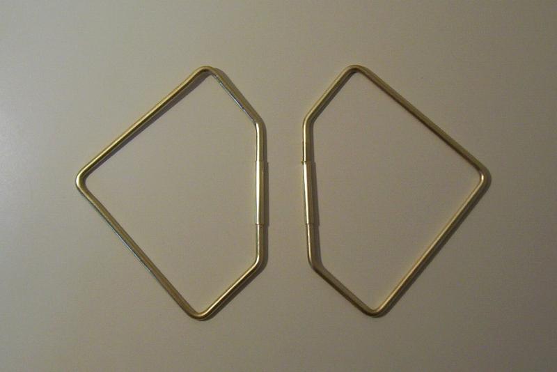
Make two brass frames using 1/8” brass rod and tube. The brass frame is a 8 cm square, cut on a 45-degree angle 2 cm past the corners. A 3 cm brass tube is slid over the joints to give a finished appearance.
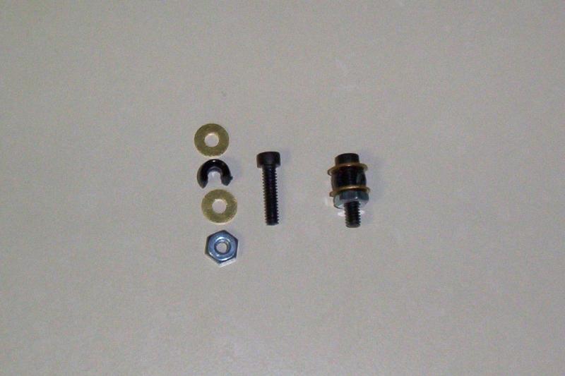
Prep the brass washers for soldering to the frame. Attach the first washer, half of a plastic bead, the second washer, and then the nut (HN0400) to the 4-40 3/4" bolt (SCA0412).
Solder on brass washers to the frame for mounting both the board plate and the motors.
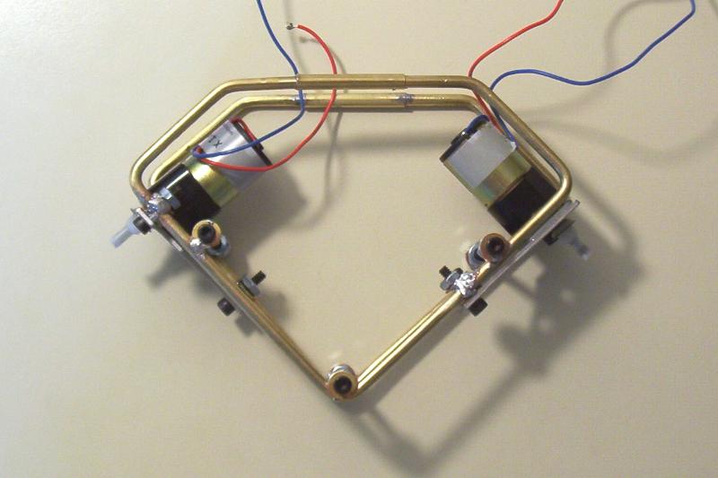
Glue brass washers (FWB4) to the 1/8” mounting holes. Attach the Nv Net and Motor boards with 4-40 1” bolts (SCA0416). Use plastic beads as spacers between the board and the Sintra plate.
Feed the Nv Net wires thru the Sintra plate and solder to the connections on the Motor boards (e.g. power, ground, Nv to 74AC245 connections).
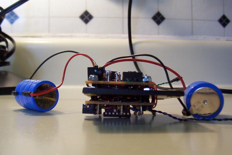
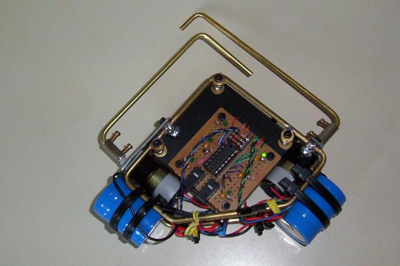
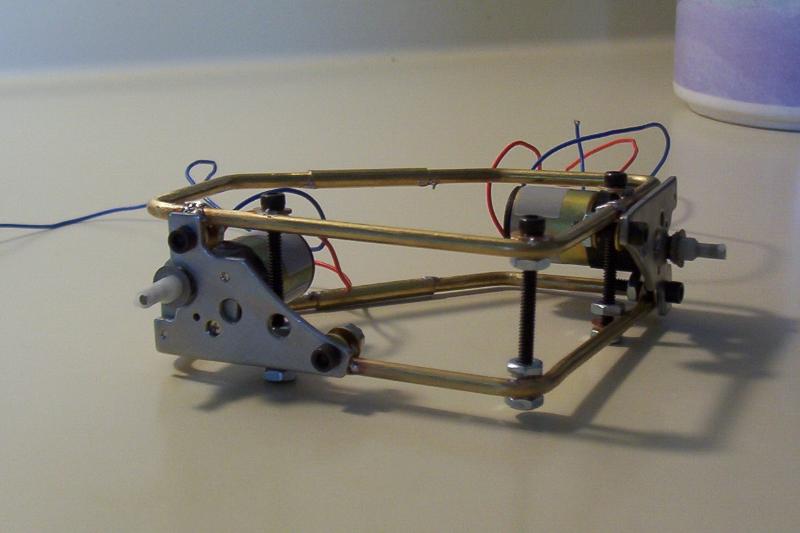
Remove the motors from the brass frame. Starting with the bottom frame, feed up the 4-40 1-1/4” bolts (SCA0420). Salvage six springs from pens, and place the first three springs on the bolts. Place the board plate on top of these springs, then add the next three springs. Bolt the top frame on and re-install the motors.
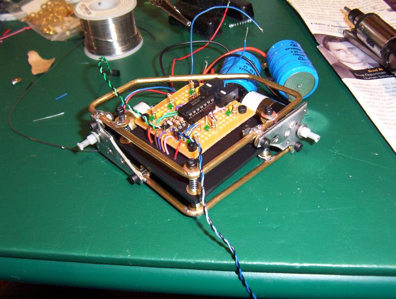
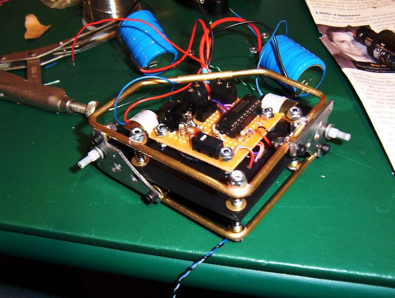
Attach the batteries to the frame with wire ties. Leave the battery closest to the charge jack slightly loose so that it can be moved for charging. Neaten the wires with ties.
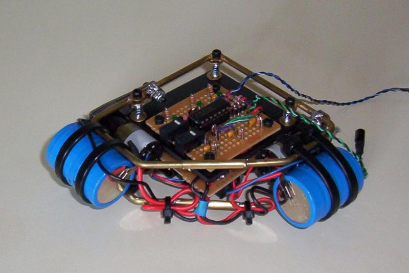
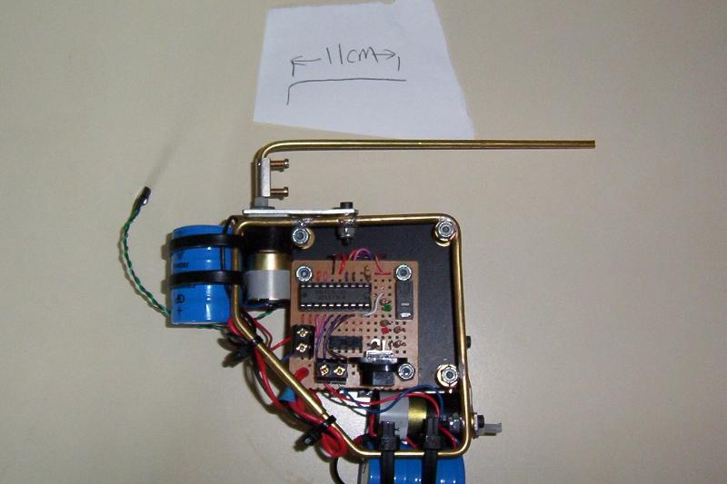
Attach the first flagella. Bend 1 cm down on a 90-degree angle and attach to the motor shaft via a terminal block. Cut 11 cm from the bend.
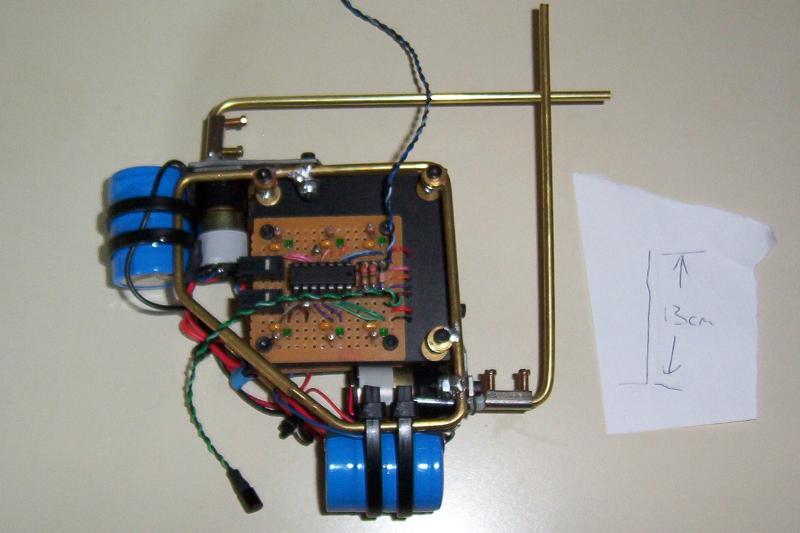
Attach the second flagella. Bend 1 cm down on a 90-degree angle and attach to the motor shaft via a terminal block. Cut 13 cm from the bend.
Bend the flagellum so that they do not strike each other during their respective range of motions. Test out and troubleshoot any mechanical problems.