A Basic Turbot Tutorial
The BEAM Turbot is a compelling machine. It displays a wide range of motions. Turbots tumble. Turbots can use its body as a rimless spoked wheel. It can even use a variety of simple bipedal gaits. All this functionality can be found in a package that is easy to build and requires little tweaking.
Turbot Anatomy
Before we get started building a Turbot, let us discuss some basic terminology. Amphitrichous bacteria serve as the design metaphor for Turbots. These little single-celled creatures have two flagella, one on each end. The flagella act as whip-like propellers, and the bacteria rotate these in order to move about the environment.

A flagellum is comprised of four main parts:
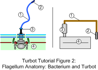
1. A long body called a filament. In bacteria, the filament is a hollow tube made of protein. In this tutorial, we will use a brass rod as the filament. Other ideas for Turbot filaments include coat hanger rods for fixed filaments and stranded wire for flexible ones.
2. A distal or end cap. This, too, is made of protein in bacteria. We will be using black antenna caps (found in most hobby stores). You can also use wire caps or heat shrink tubing.
3. A hook to connects up the filament. For our purposes, we will be using a terminal block to attach the flagellum to the motor shaft.
4. The filament connects to an organelle, which spins the flagellum. Bacteria have something very similar to a motor and this is one of the wonders in nature. Lacking such nice molecular motors, we will build a Turbot with high-torque gear motors.
Turbot Nervous Nets
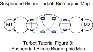
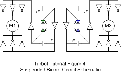
On to the beast's brains. For our basic Turbot, we will use the simple phototropic Suspended Bicore.
Sensor placement is what is important here. By placing the sensors in a cross-over or X-shaped pattern, the mechanics handle what would otherwise require a multiplexor or reverser.
Parts List
2 - 74AC240 IC4 - 1µF Monolithic Capacitors
4 - Photodiodes (Siemens SFH 205f)
1 - 2mm white Sintra
1 - 3mm black Sintra
2 - DC Gear Motors (Solarbotics GM3)
1 - 4-AA battery pack (Radio Shack 270-391A
1 - Power Switch (Solarbotics SWT1)
2 - European terminal blocks (Radio Shack 274-679)
2 - 4-40 x 1" Bolt (Micro Fasteners SCA0416) 2 - 4-40 x 1/4 " Bolt (Micro Fasteners SCA0404) 4 - Lock Nuts (Micro Fasteners N10440) 4 - Washers (Micro Fasteners FWS04) 1 - 1/8" Brass Rod
1 - 5/32" Brass or Aluminum Tube
4 - Black antenna caps
Step 1: Cut the Sintra
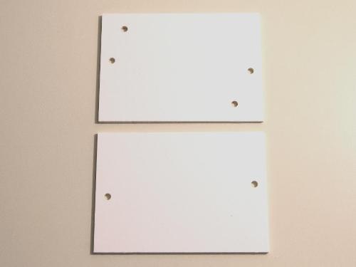
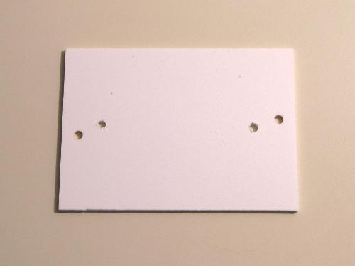
Cut out the body from 2mm Sintra.
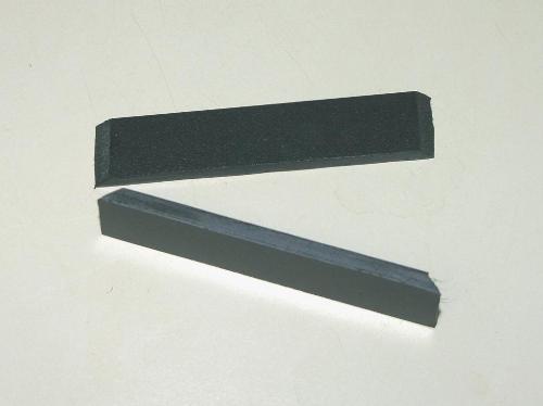
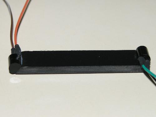
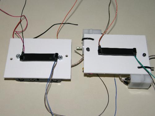
Cut out the sensor mounts from 3mm Sintra. The dimensions are 4.8cm by 1cm. Cut the sides on a 45-degree angle.
Step 2: Attach the motors
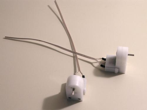
Solder wires to the motors.
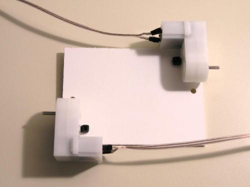
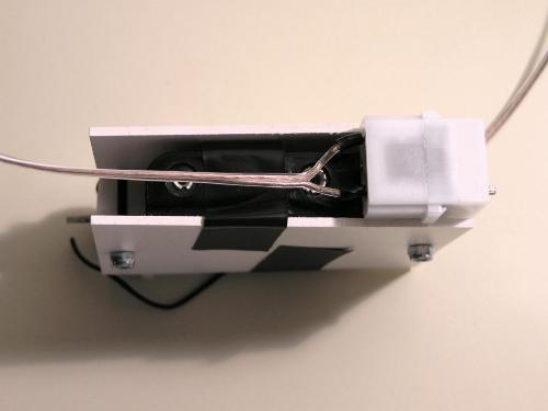
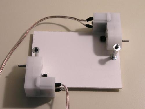
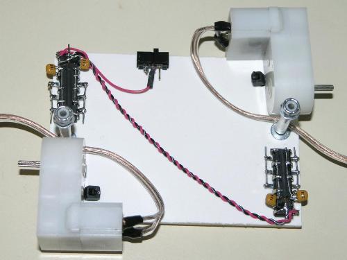
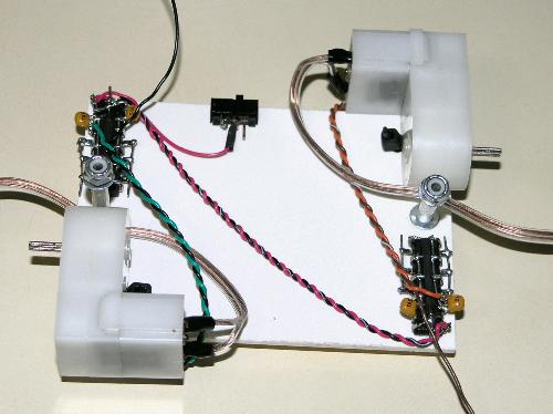
Wire-tie the motors onto the top.
Step 3: Attach the battery pack
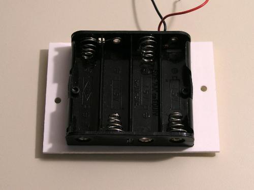
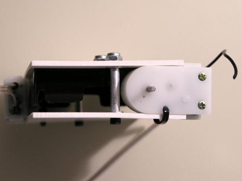
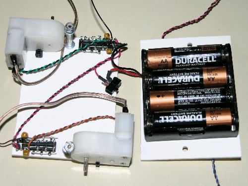
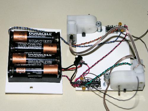
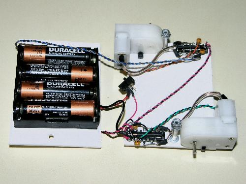
I find that many battery holders have different mounting holes. To determine where to mount the battery holder, I first place the holder on the bottom and screw the top down. The motors will keep the battery holder in place. I use tape to secure it.
Next, unscrew and remove the top. Mark the battery holder's holes. Drill these.
Screw the battery holder in place.
Step 4: Assemble the body
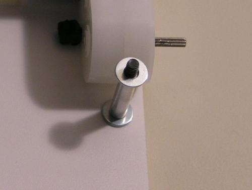
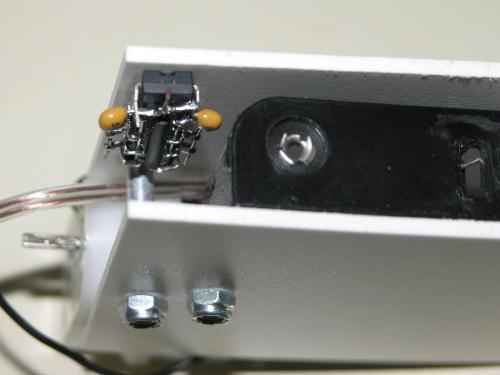
From the piece of aluminum or brass tubing, cut two 17mm sections. Use tubes as stand-offs on the mounting screws. The order goes: washer, tube, washer.
Screw the top to the bottom to test the fit. The Sintra should lay flat.
Step 5: Build the Brains
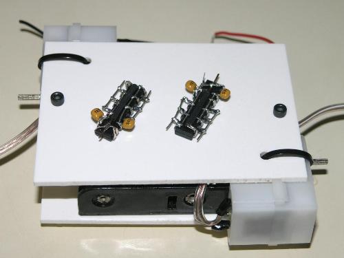
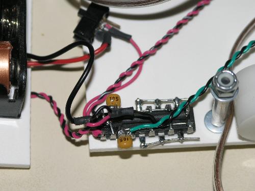
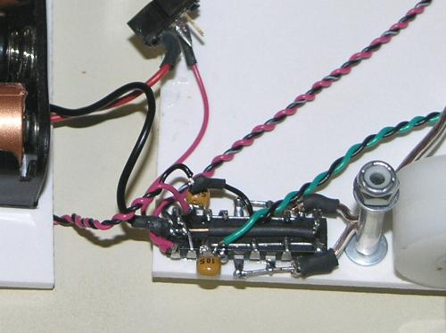
Free form two suspended Bicores. Use 74AC240 since these will be driving motors. We want a good range of time, so use 1uF for the capacitors. Click here for a tutorial.
Glue the Bicores to the top of the body, on the same side as the motor. Once secured, run a Vcc and Gnd lines between the two 74AC240 chips. Run a Vcc line from one chip to a power switch. Position the switch about midway between the two motors.
Step 6: Attach the Sensors
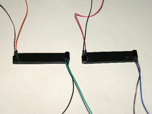
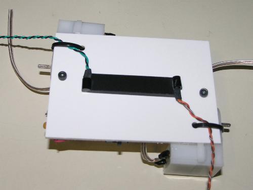
The sensors attach to a piece of Sintra and are placed in a cross-over pattern. In this step, you will attach the photodiode sensors to the 45-degree cuts you made earlier. This ensures that the sensors are detecting the light at opposite corners of the body.
Solder wires onto the Photodiodes. Use a six color scheme. The cathodes (negative, notched lead) will be connected to each other, so use the same color for each pair's cathodes (I chose black for the left Bicore and brown for the right). The anodes (positive lead) will connected to the Bicore, so use a different color for each photodiode (I chose violet and green for the left Bicore, orange and blue for the right Bicore).
Glue the photodiodes to the Sintra.
Step 7: Attach the Sensors to the Body
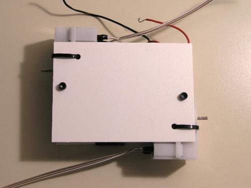
Glue the sensors to the body. Run the wires on the top thru the wire ties. This helps to protect the wires from being pulled out.
Step 8: Attach the Sensors to the Brain
Solder the top photodiodes to the Bicore. The left photodiode's anode goes to the left Bicore on pin 17 (green wire). The right photodiode's anode goes to the right Bicore's pin 17 (orange wire). There is already a capacitor on pin 17, simply hook the wire onto it. Take care not to create a bridge.
Step 9: Add Power
Connect the Gnd line from the battery pack to the left Bicore's Gnd connection (pins 1, 10, 19). Connect the battery pack's Vcc to the switch.
Test for short circuits. Keep a hand on the batteries and pay attention to their temperature. If you have a multi-meter, connect it up to the Bicores' Vcc and Gnd. Otherwise, use a LED. Turn on the switch. The batteries should remain cool and the meter (or LED) should indicate power. If not, immediately turn the switch off and check for places where Vcc and Gnd lines may have accidentally been connected.
Step 10: Attach the Sensors to the Brain
Solder the bottom photodiodes to the Bicore. The left photodiode's anode goes to the left Bicore on pin 2 (violet wire). The right photodiode's anode goes to the right Bicore's pin 2 (Blue wire). As with before, hook the wire onto the capacitor on pin 2.
Step 11: Connect the Sensors together
There are two pairs of sensors. If you used a common color for each pair's cathodes, identifying what goes to what should be straightforward. Connect the top left to the bottom right (black wire) and connect the top right to the bottom left (brown).
Step 12: Test the motors
Repeat the power and short circuit test you did in step 9. Make certain that the Bicores are powering up before continueing.
Next, determine how best to connect the motors. Cover the top photodiodes with a piece of electrical tape. Tilt the bottom photodiodes up and towards a light source. Strip the motor wires.
With the power on, place the first motor's wires onto the Bicore. The motor should turn forward (toward you) for a good deal of time, then turn in reverse for a short spurt, then resume going forward. If this is not the case, then check the Bicore's connections. Mark which wire goes to which Bicore lead.
Repeat this for the second motor on the other Bicore. You want both motors to turn in the same direction, so that the finished Turbot will flip towards the light. Again, mark which wire goes to which lead.
Step 13: Connect the Motors to the Bicores
Once you figure out the motor wiring, go ahead and solder the motors to the Bicores.
Step 14: Build the Flagella
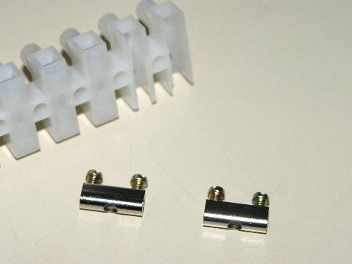
Take the terminal strip and remove the screws from two of the terminal blocks. Cut the terminal blocks from the plastic strip.
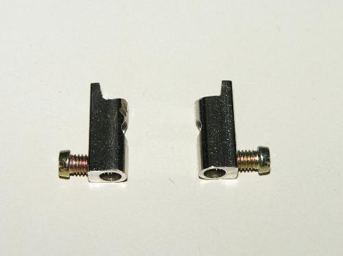
Use a Dremel or similar tool to shave 1/8" off of the terminal blocks.
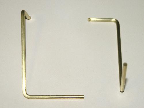
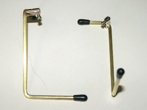
Cut a 1/8" brass rod into two pieces, 13.5 cm in length. Bend 90-degrees at 3 cm and 4 cm. The result should be 3 cm spur, 6.5 cm leg, and 4 cm foot.
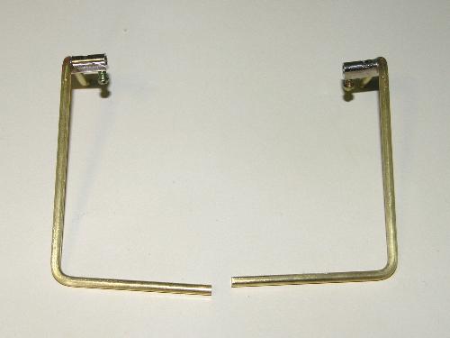
Fit the shaved end of the terminal blocks into the bend between the spur and leg. Solder the blocks to the brass. Use a 100-Watt solder gun or similar tool.
Cap the ends with black antenna caps.
Step 15: Finishing up
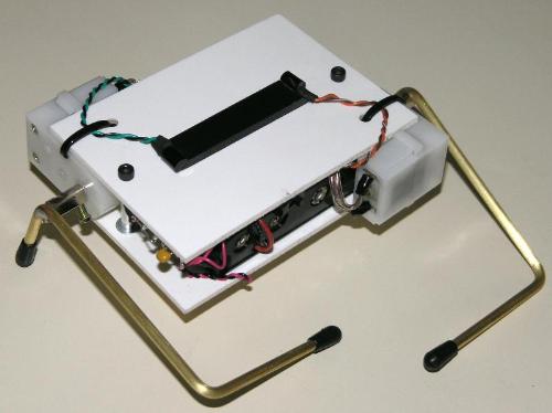
Bolt the body together. Glue the power switch in place. Attach the flagella. Let'er rip.
Have fun!
J Wolfgang Goerlich
June 2006
