Building a Solar Engine Dynamometer
Assembling BETS1
Building the Base
Finishing Up
Conclusion
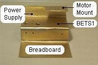
Building the BaseIn this section, we will be looking at building the dynamometer’s base. At a minimum, the base must provide enough space to mount the BETS1, the breadboard, and the optional power supply. It must also provide a motor mount that meets the design goals of supporting different test motors, and shielding the BETS1 from ambient light. There are, of course, multiple ways to build a base that meets these requirements. The base I am presenting represents the one that was the easiest to build, and most tolerant in cutting and bending. Note: The width of the test station is set by the width of the breadboard. I am using the Modular IC Breadboard (Radio Shack Part # 276-175), which 3-5/8" wide. I am using a width of 4 inches, or 10 cm, in order to leave a margin around the breadboard. Adjust your width according to your breadboard. Parts list:
1 x Sintra 15cm x 10cm (Base for Breadboard and BETS1) |
|
|
With that, on to step one: select your mouse. I elected to purchase a new mouse, and based my purchase on several points. I chose the Logitech First Wheel Mouse, which supports USB. The design is symmetrical, enabling me to re-use the mouse shell as a body of another BEAM robot. The mouse comes with a USB to PS2 adapter, which I have used in a portumvore (powering a solar engine from a computer port). Finally, the mouse is inexpensively priced at less than $10 USD. Parts list: 1 x Mouse2 x Sintra 1 cm x 2.5 cm (Spacer) 1 x Sintra 1.8 cm x 2 cm (Holder) |
|
|
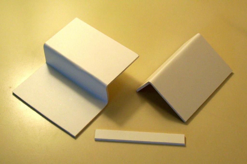
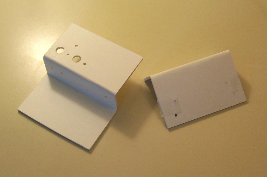
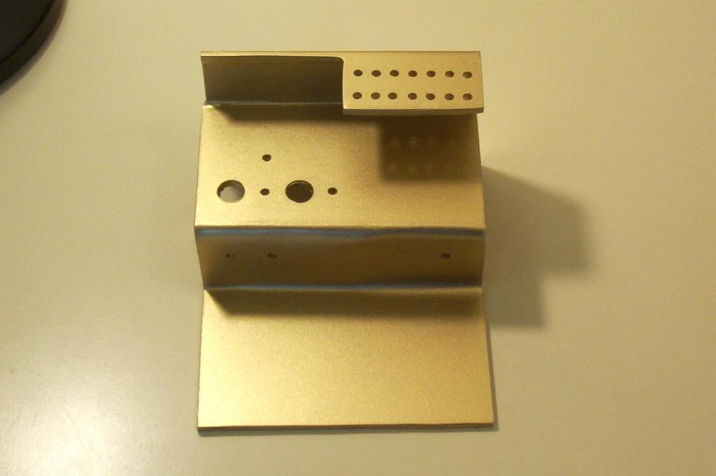
Cut out the Base, Back, and Back Brace from the Sintra. Mark where you are going to bend the Sintra. |

|
|
Bend the Sintra into shape. |
|
|
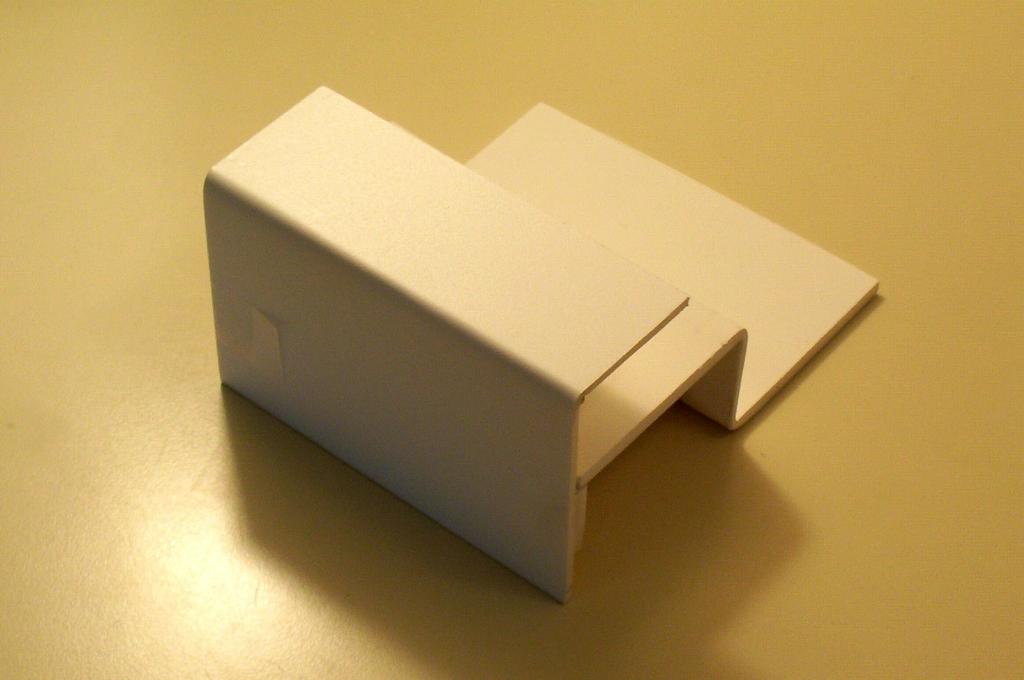
Tape the back brace into place, and make sure that the front and back line up properly. If necessary, trim off excessive Sintra. |
|
|
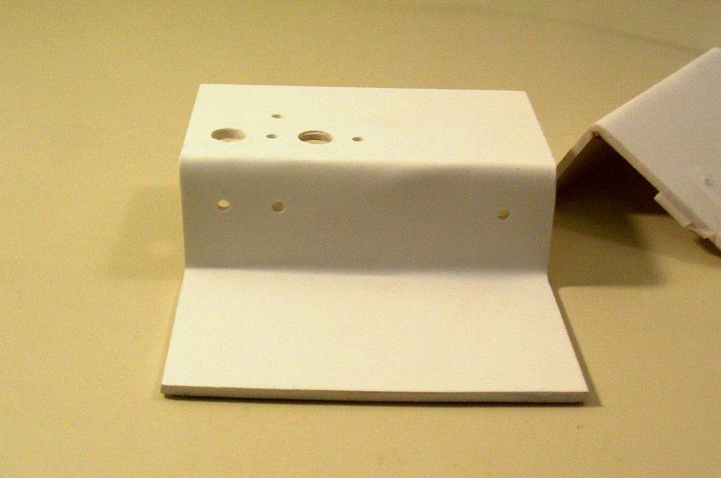
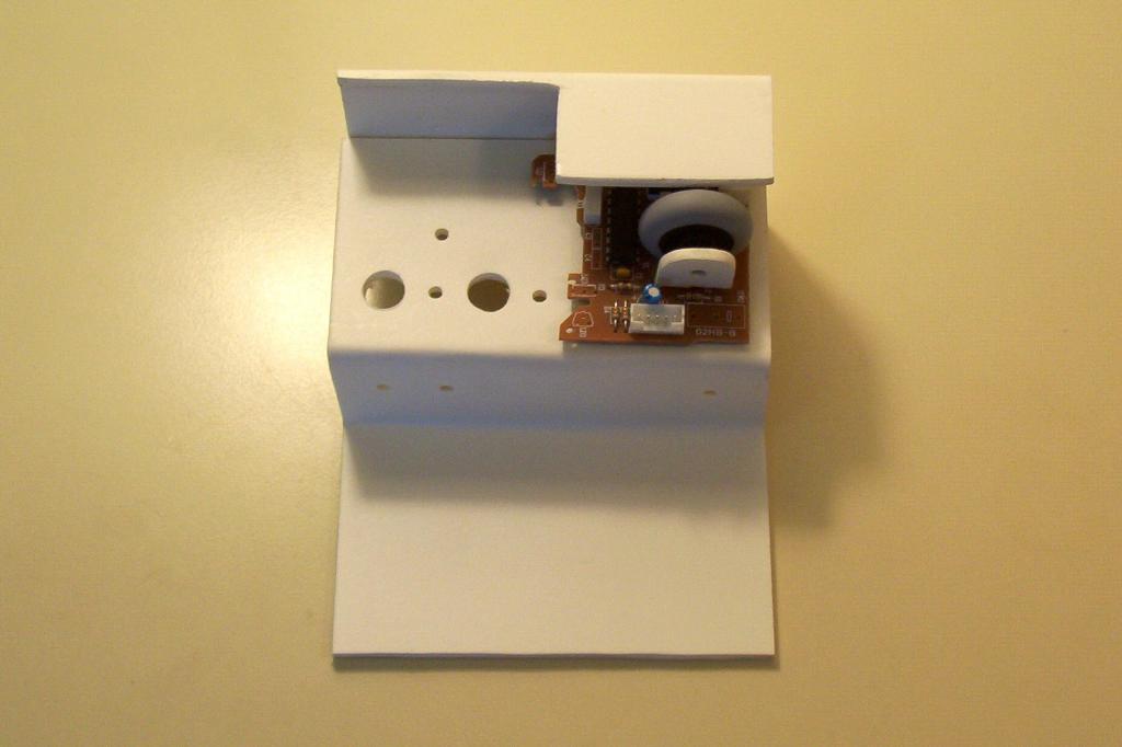
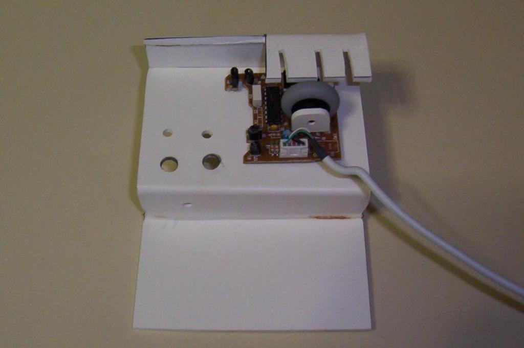
Drill eight holes in the base, and three holes in the back. In the top of the base, drill two holes for your potentiometers. If you build a power supply, these can be used to adjust the voltage and current. Otherwise, these pots can be used on the breadboard for tweaking the resistor values. I used 3/8” holes for the pots. Next to the pots, drill two 1/16” holes for the pot’s wiring. Drill a final 3/8” hole for the output of the power supply above the holes for the pots. Drill three more 1/16” wiring holes on the front of the base. The first two are for the optional power supply output. The final hole is for the motor wires. On the back, drill two 5/32” holes thru the back into the back brace for pining while gluing. Drill a final 1/16” wiring hole for the motors on the back brace. |
|
|
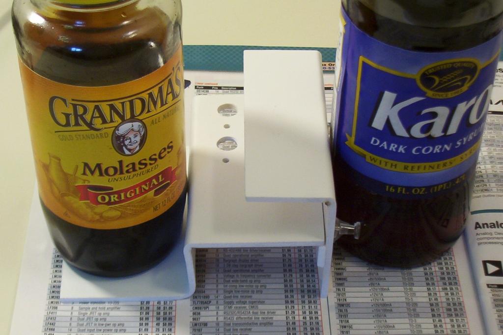
Next, glue the back brace onto the back, using pins in the holes just drilled to ensure alignment. Once that glue sets, glue the breadboard base onto the back. Use a weight such as a bottle of molasses to keep the base flat while the glue dries. |
|
|
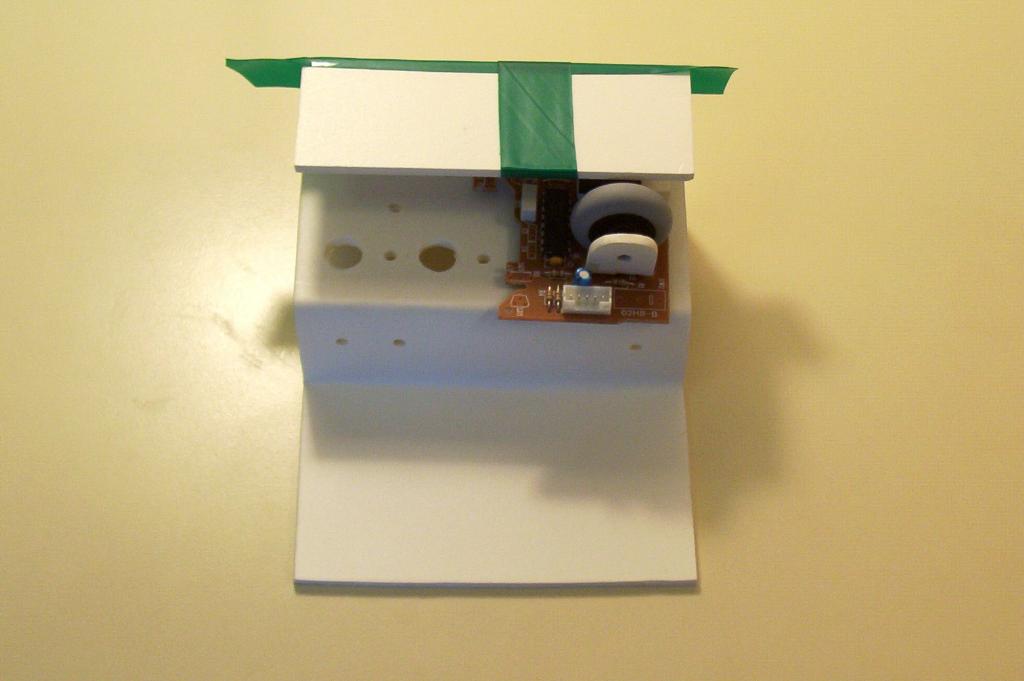
Now take the BETS1 interface that you created, and lay it on the base. Measure and mark an area slightly larger than the size of the mouse. The objectives are to provide enough shade from ambient light, while at the same time providing enough space for the mouse wheel to spin freely. |
|
|
Cut out the marked area. |
|
|
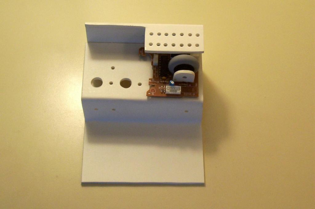
With the BETS1 in place, we can determine where and how to mount the motors. There are two goals here. First, we want to be able to mount motors of varying sizes. Second, we want to be able to mount two motors to simulate a load. We will hold the motors in place with zip ties, so we need to either cut slits for these ties or drill various holes. If you are using slits, then cut them into the motor mount. Otherwise, drill two series of 7/64" holes into the motor mount. The first series (top in photo) are for the back of the motor, and the second (bottom in photo) are for the front of the motor. |
|
|
Remove the BETS1. Prepare the base by sanding with 200, 400, and then 600 Grit sand paper. Then paint the base. This concludes the Base assembly instructions. |
|