Building a Solar Engine Dynamometer
Assembling BETS1
Building the Base
Finishing Up
Conclusion
Assembling BETS1There are several design decisions to make when building a BETS1. It is worth considering these options, as the choices can lead to differences in test results. After discussing these considerations, I provide a description on building a BETS1. While specifically designed for the dynamometer, this BETS1 can be used separately. Whether to use a PS2 or USB adapter is the first decision. In shape, the PS2 is short and round, while the USB is wide and somewhat flat. The benefits of PS2 are that the mice are more plentiful and cost less. The downside of PS2 is that you risk damaging your computer if you plug or unplug a PS2 mouse while the computer is running. To me, this is the primary advantage of USB: you use a USB mouse for hot swapping (that is, plugging or unplugging the BETS1 while the computer is on). Another advantage of using USB is that multiple mice can be run at the same time, meaning you can test using the dynamometer and still make use of the computer. The second decision is whether to use the X-Y axis or use the scroll wheel. Many of the original mice lacked the scroll wheel, so the decision may already be made if you are using a salvaged mouse. Likewise, many new mice are optical, and only have a scroll wheel (X-Y axis being an optical sensor). I have found the scroll wheel ideal as the testing does not contend with the mouse for cursor movement, and the software provided at the end of this article tests for scroll movement. The final choice is in mounting the solar engine’s motor. This is the single most important aspect in constructing a BETS1. Alignment, pressure, and friction all come into play when placing the motor in contact with the BETS1. If you elect to build the BETS1 alone, then experiment with motor placement; otherwise, we will cover mounting the motor when we add the BETS1 to the base. |
|
|
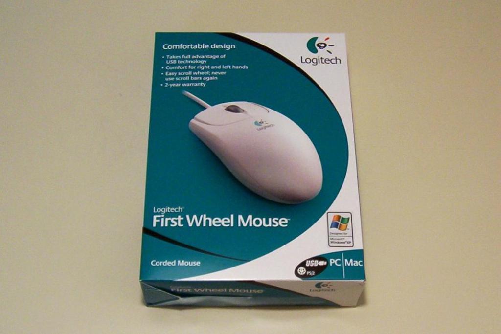
With that, on to step one: select your mouse. I elected to purchase a new mouse, and based my purchase on several points. I chose the Logitech First Wheel Mouse, which supports USB. The design is symmetrical, enabling me to re-use the mouse shell as a body of another BEAM robot. The mouse comes with a USB to PS2 adapter, which I have used in a portumvore (powering a solar engine from a computer port). Finally, the mouse is inexpensively priced at less than $10 USD. Parts list: 1 x Mouse2 x Sintra 1 cm x 2.5 cm (Spacer) 1 x Sintra 1.8 cm x 2 cm (Holder) |
|
|
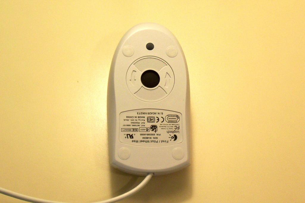
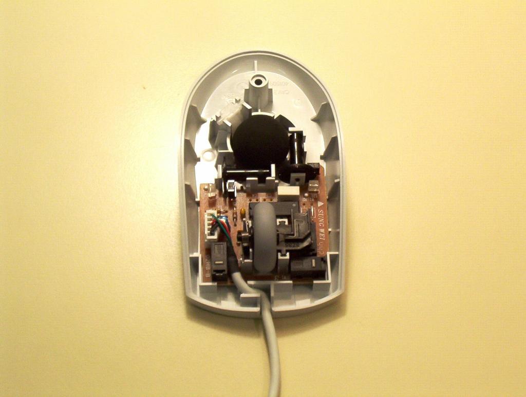
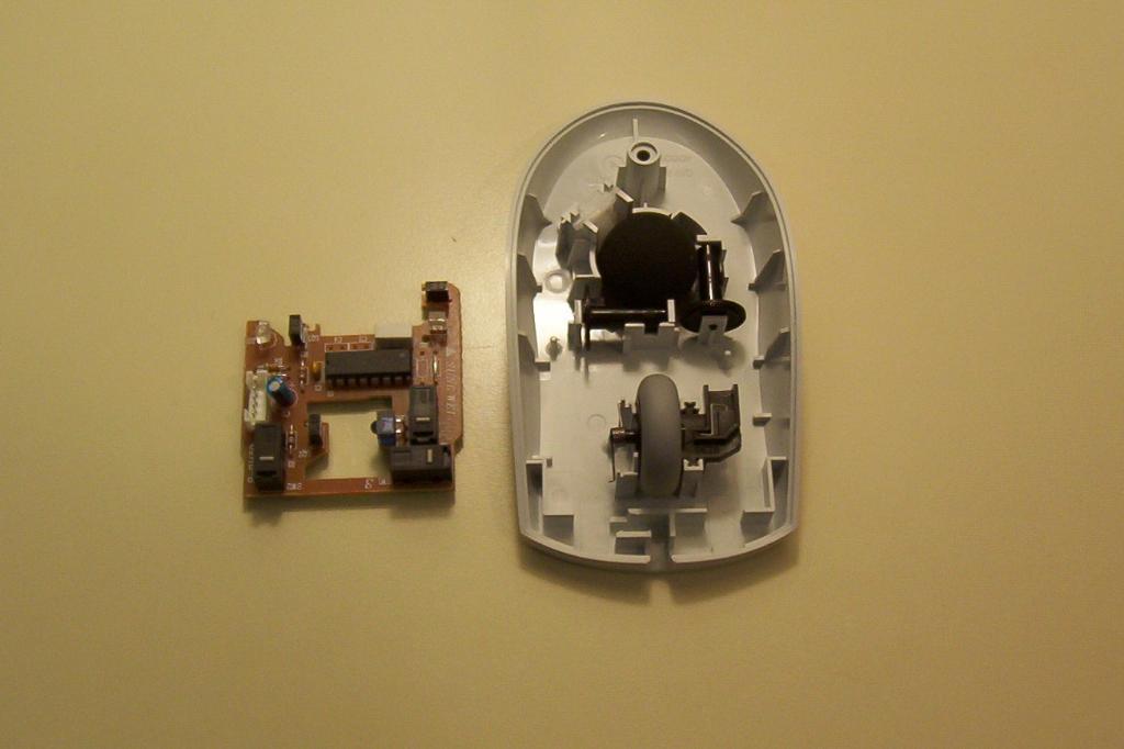
Most mice are contructed with a single screw in the rear, and clips near the mouse buttons. Unscrew the mouse, and remove the top cover. |
|
|
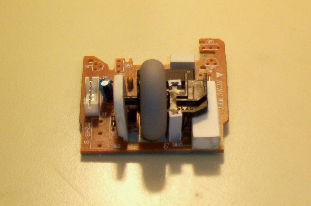
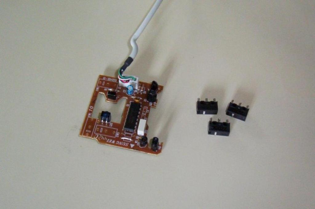
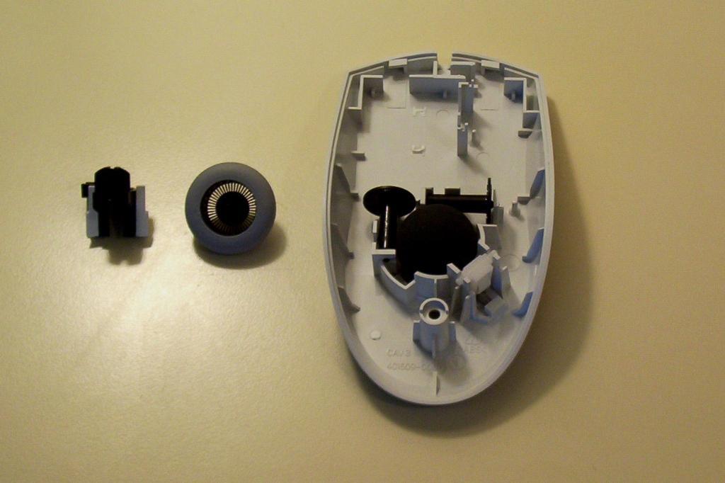
First remove the scroll wheel, then remove the mouse interface board, and replace the scroll wheel. You may notice that the scroll wheel has two springs. The first (left in the photo) is the tensioner spring, and this allows people to click the scroll wheel like a mouse button. The second is the detent, and it is built into plastic base and causes the scroll wheel to click when turned (right in photo). Remove the USB cable from the mouse board. |
|
|
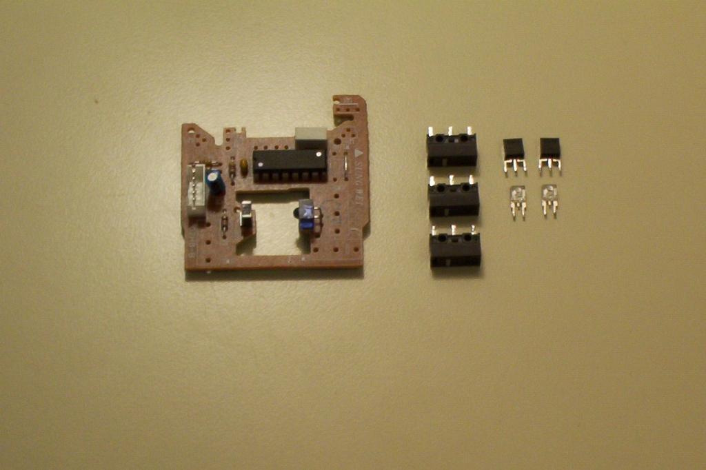
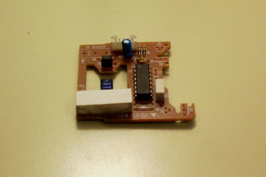
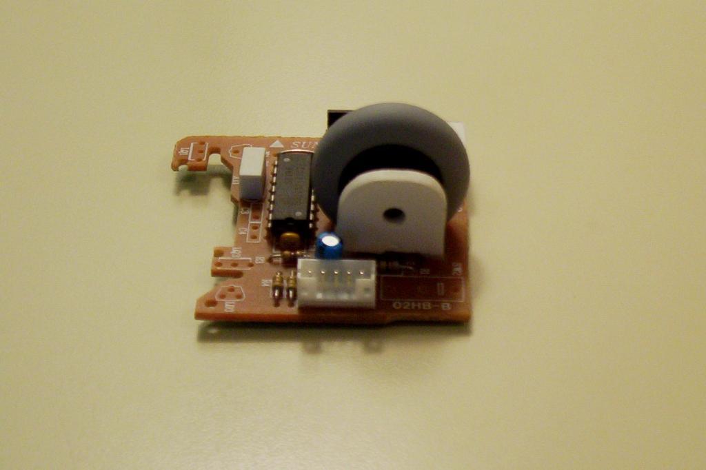
Desolder the mouse switches, then the X-Y axis LEDs and Phototransistors. I safely performed this procedure on the Logitech mice using the Sung Wei 442C (02HB-B) mouse interface boards. If you have a different board, or if you are unsure of the board, then cover the LEDs and Phototransistors with heat shrink tubbing. |
|
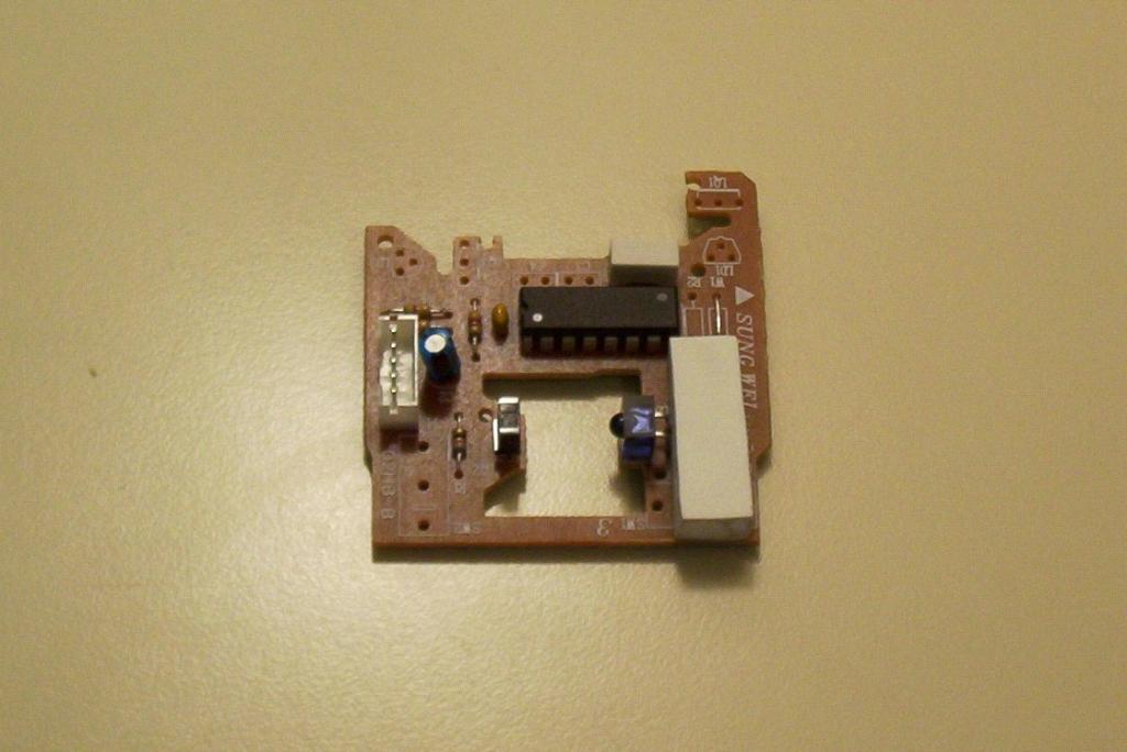
| Make a spacer by taking two Sintra pieces measuring 1cm x 2.5cm. Glue these together. When the glue sets, glue these onto the mouse board where the switches were. |
|
|
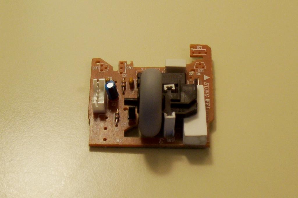
Remove the detent from the scroll wheel assembly. There are two stands that hold the wheel assembly in place on the mouse body (top left in photo). Remove these stands from the mouse body using either firm pressure or an exacto knife, then glue these stands onto the wheel assembly. You can now screw the mouse body back together, and store it for use elsewhere; for example, as a body in another robot. |
|
| Now glue the mouse assembly onto the Sintra base. Take care not to glue the wheel itself. |

|
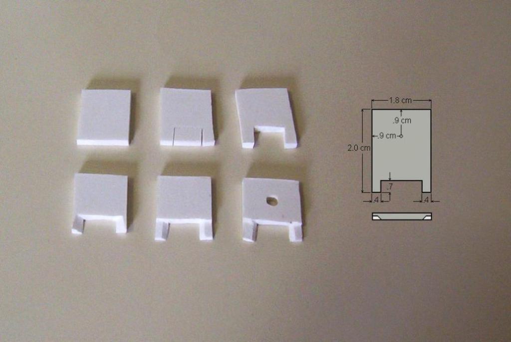
| The next step is to create a holder for the other side of the mouse wheel assembly. To create this holder, follow these six steps: 1) cut a 2cm x 1.8cm piece of Sintra; 2) Cut two 7mm slits into the Sintra 4mm from the sides; 3) Scar between these two slits and break the Sintra along the line to form two legs; 4) Cut 45 degree angles across these legs so as to fit the mouse board; 5) Cut the legs in half; 6) Drill a hole larger than the house axel, 9/64". |
|
| Sand and shape the holder so that it fits snuggly against the mouse board. Glue the holder into place by applying glue to the back of the IR transistor and the bottom of the holder. Ensure that the mouse wheel spins freely. |

|
|
This concludes the BETS1 assembly instructions. At this point, you can build a test stand by mounting a motor to turn the scroll wheel. Better yet, you can build the dynamometer base, then mount the BETS1 in place for a complete test stand. |