Building a Solar Engine Dynamometer
Assembling BETS1
Building the Base
Finishing Up
Conclusion
Finishing Up the DynamometerWe will be adding the motor, the BETS1, and the breadboard to the base in this final section. Mounting the motor is the critical mechanical factor in achieving repeatable test results. Slight variations in pressure and alignment will cause broad differences in results. In terms of pressure, you want the motor wheel to be snug against the BETS1 wheel. The motor will be overloaded if it is too tight, but the wheel will spin freely or slip against the BETS1 if it is too loose. Likewise, the motor wheel must be aligned with the BETS1 wheel. Otherwise, the motor will waste some of its energy without turning the BETS1. In order to support different sizes and types of motors, I have made a trade-off in motor dependability. Using wire ties for motor mounts and Velcro to secure the BETS1 practically ensures that the motor alignment will require adjustment every few tests. If you intend to test with one type of motor only, then I suggest you add a strip of Sintra to hold the motor in place and consider gluing the BETS1 down. This will reduce the need for motor adjustments, but restrict your ability to swap out the test motor. Parts list:
1 x Pager Motor (Solarbotics RPM2) |
|
|
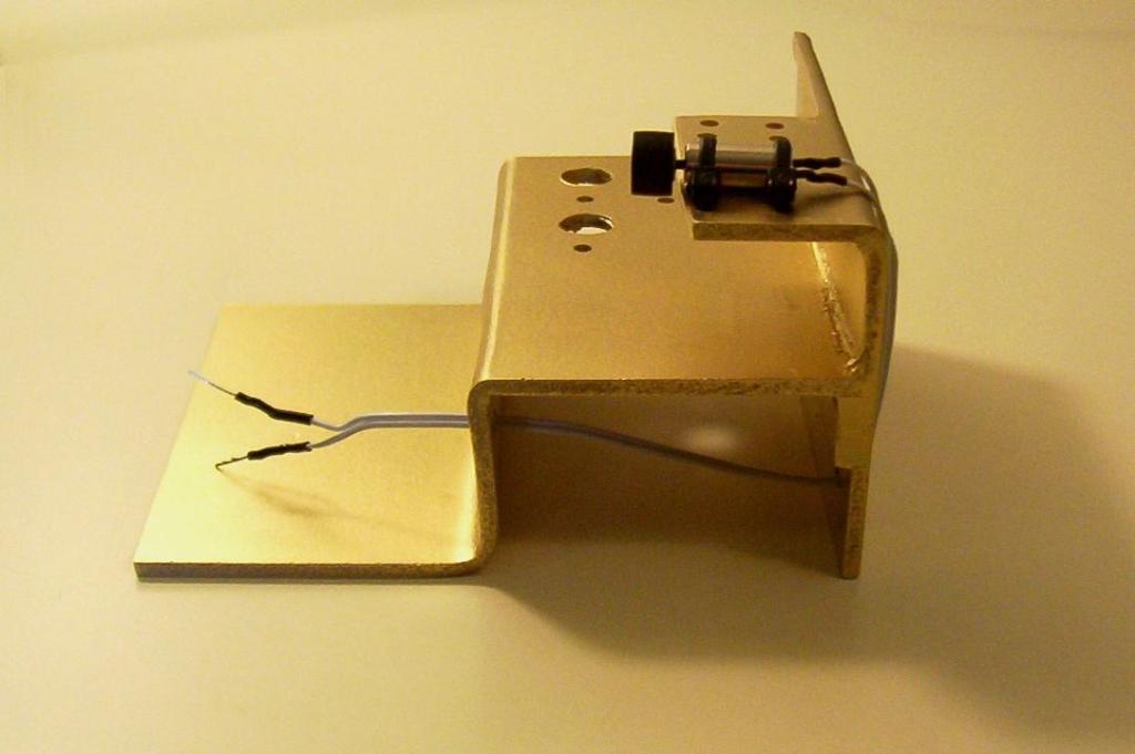
Attach the wheel to the pager motor. Solder the wire on to the motor, then to the solid wire for use on the breadboard. I am using leads from LEDs. Using the wire ties, mount the motor approximately 1/3 of the way in on the motor mount. This position will leave enough space for mounting a larger motor in the future if desired. |

|
|
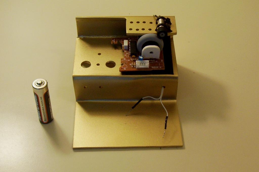
Glue thin strips of Sintra underneath the BETS1 to raise it into position. This is useful in correcting any differences in tolerances that may have occurred between measuring and bending the Sintra. Attach a section of Velcro to the Sintra strips. Place two sections of Velcro on the base where the BETS1 will mount. Once the glue on the Velcro is dry, position the BETS1 so that it rests lightly against the motor, too much pressure will create too much strain on the motor. Test the motor with a 1.5 AA battery to ensure that the motor can easily spin the BETS1 wheel without slipping. If necessary, adjust the BETS1 until achieving a proper balance of pressure and alignment with the motor. |
|
|
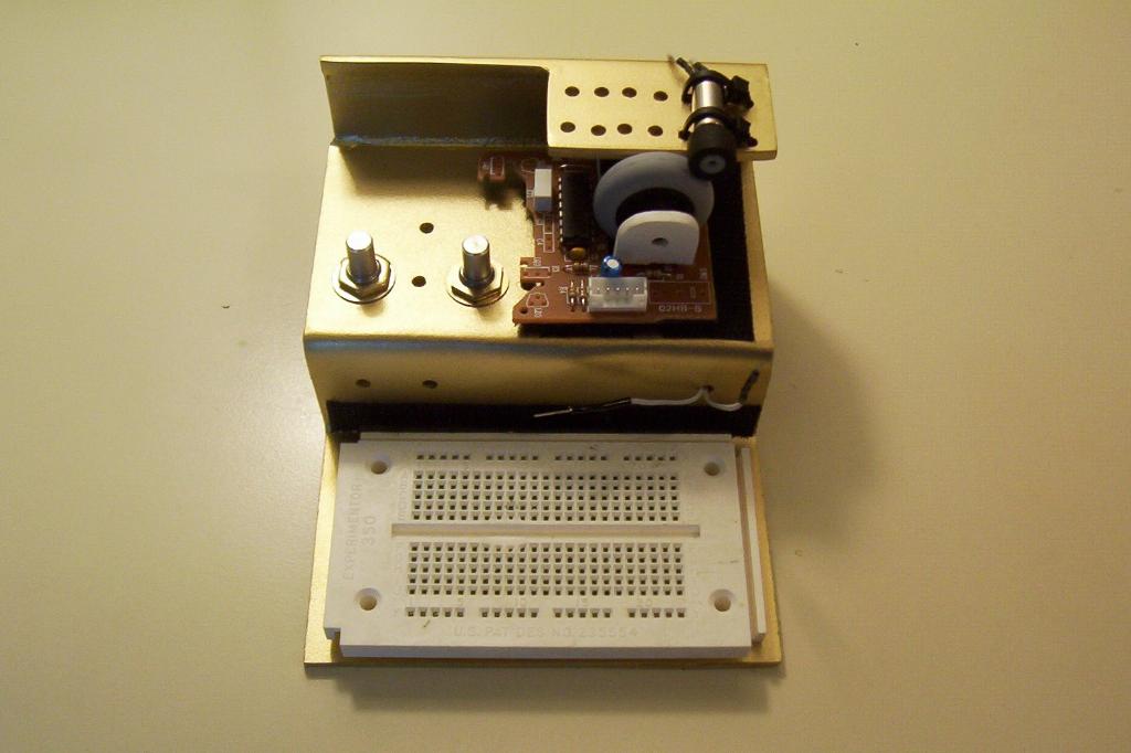
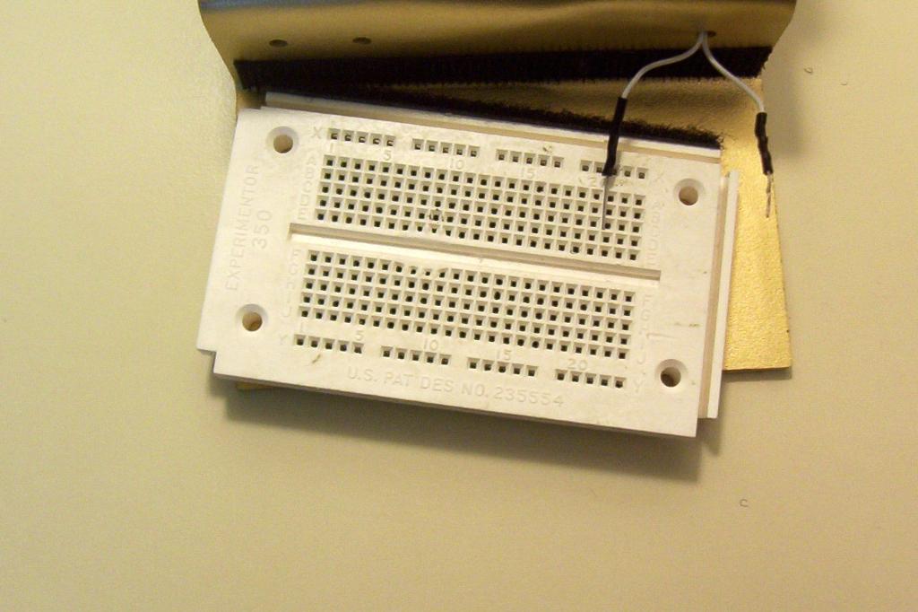
Apply the velcro tabs to the base, and to the breadboard. This will allow you to use your breadboard as part of the dynamometer, as well as use it separately. |
|
|
Finally, install the two 10K pots into the holes you drilled earlier in the base. If you elect to build a power supply, these pots will be used to control voltage and current. Otherwise, you can use these pots to test how varying resistors affects the solar engine's performance. |
|